This article will introduce the HY16F198 with Hall Sensor (WCS1800) for AC current measurement. The maximum measurable current range is from 0.1A to 17.68A. The experimental data from 0A to 17.6A are compared. The Agilent 34401A and HY16F198 are used to communicate with each other. The signal calculates that the maximum error rate of the AC current obtained between different frequencies of 45 Hz, 50 Hz, and 60 Hz can be controlled within 3%.
Second, the principle descriptionMeasuring principle
The WCS1800 converts the sensed AC current into an output voltage (Vout), and the output voltage (Vout) component is a signal consisting of a mixture of (Vac) AC voltage signal and (Vdc) DC voltage signal, measured using HY16F198. Output voltage (Vout) signal, and analyze the ADC Count value through the algorithm to convert the relative sensed AC current load. However, it should be noted that the maximum error of the output voltage per 1 ampere (A) transferred by Hall Sensor (WCS1800) is plus or minus 6mV. The detailed Hall Sensor specification table is shown in the next page of the electrical characteristics table.
Hall Sensor (WCS1800) has its own output voltage (Vout) with Vac AC voltage plus Vdc DC voltage mixing component, and Vdc value is 1/2 Vdd. Therefore, this application uses HY16F198 to set VDDA voltage to 3V, and Set the ADC input reference voltage amplification factor to VREF*1/2 (VREF= VRPS-VRNS) in the ADC buffer. If the buffer is set to this limit, the input voltage can be accurately measured to the maximum range of 1.5V. However, such a connection cannot measure the Vout output voltage range of the Hall Sensor, so it is necessary to add two voltage dividing resistors externally, and divide the 10k ohm resistance between the AIO(0) and VDDA and VSS of the ADC. The voltage is measured, and the measured voltage value is then calculated and analyzed by the AC signal to determine the induced AC current, and the LCD display is used to display the current value.
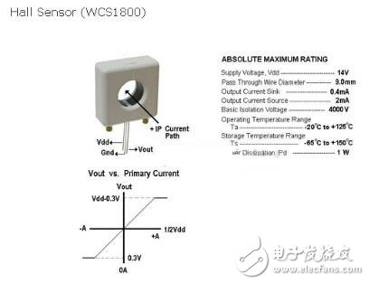
Figure 1 Hall Sensor
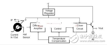
Figure 2 block diagram
Control chipIntroduction to MCU: HY16F Series 32-bit High Performance Flash MCU (HY16F198)
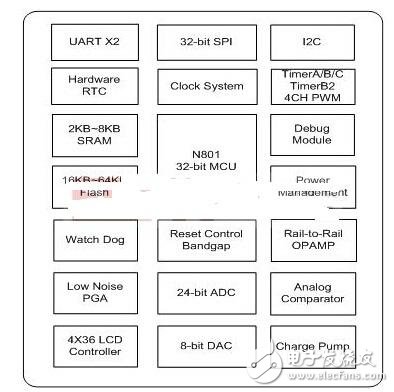
Figure 3 HY16F198
(1) Adopt the latest Andes 32-bit CPU core N801 processor.
(2) The voltage operation range is 2.2~3.6V, and the operating temperature range is -40°C~85°C.
(3) Support external 20MHz quartz oscillator or internal 16MHz high-precision RC oscillator, with a variety of CPU operating frequency switching options, allowing users to achieve optimal power saving planning.
(3.1) Operating mode 350uA@2MHz/2 (3.2) Standby mode 10uA@32KHz/2 (3.3) Sleep mode 2.5uA (4) Program memory 64KBytes Flash ROM (5) Data memory 8KBytes SRAM. (6) BOR and WDT Function to prevent CPU crashes.
(3.2) Standby mode 10uA@32KHz/2
(3.3) Sleep mode 2.5uA
(4) Program memory 64KBytes Flash ROM
(5) Data memory 8KBytes SRAM.
(6) BOR and WDT function to prevent CPU crashes.
(7) 24-bit high-precision ΣΔ ADC analog-to-digital converter (7.1) with built-in PGA (Programmable Gain Amplifier) ​​up to 128 times magnification.
(7.2) Built-in temperature sensor.
Third, system design
Hardware description
HY16F198 with Hall Sensor connection circuit is as follows, AIO1 is connected with Vout of Hall Sensor, AIO0 is connected between VDDA and VSS through 10k voltage component voltage circuit, so that AC voltage signal with 1/2VDDA can be measured.
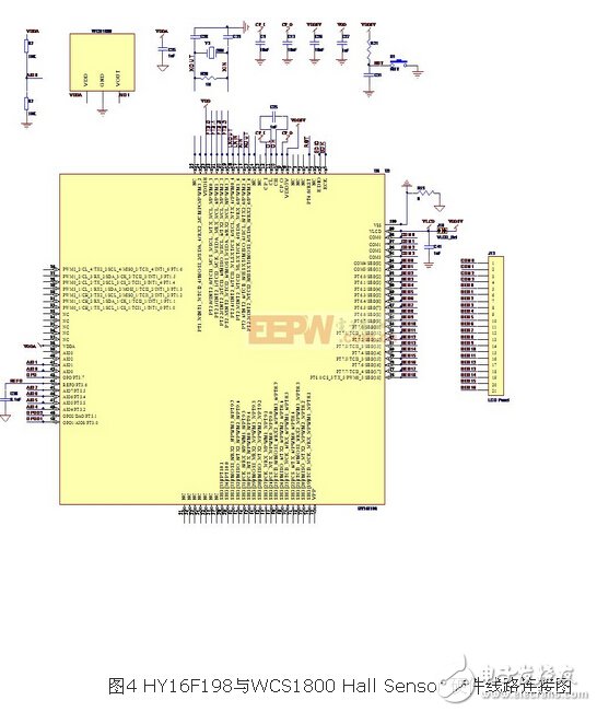
Main component introduction
(1) MCU: HY16F198, function is to measure electrical signal, control, and operation include function to store calibration parameters.
(2) LCD Display: responsible for displaying the measured current value.
(3) 10K ohm divider circuit: Mainly used as a voltage divider circuit, it can measure the AC voltage signal with 1/2VDDA.
(4) Hall Sensor: Converts the sensed AC current into a mixed voltage output signal of Vac plus Vdc.
Software description
This article refers to the address: http://TIcle/271787.htm
Program flow chart
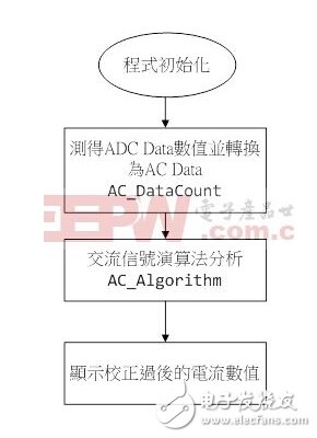
Function instructions:
1. void AC_DataCount(int index, int ADC_Data) : Converts the measured ADC Data to AC Data.
Int index : Represents the number of measured ADC Data data.
Int ADC_Data : The ADC Data value measured using the HY16F198 ADC.
2. long long AC_Algorithm(void) : AC Data calculates the current value through the AC signal algorithm.
First, the sample program
/*------------------------------------------------ ----------------------------*/
/* MAIN funcTIon */
/*------------------------------------------------ ----------------------------*/
Int main(void)
{
Long long AC_Value;
DisplayInit();
ClearLCDframe();
Delay(10000);
DisplayHYcon();
Delay(1000);
MCUSTATUSbits._byte = 0;
Count=0;
InitalADC();
SYS_EnableGIE(7,0x1FF); //Enable GIE(Global Interrupt)
While(1)
{
If(MCUSTATUSbits.b_ADCdone) //b_ADCdone=1 execute below
{
MCUSTATUSbits.b_ADCdone=0;
AC_Value = AC_Algorithm(); // To do AC algorithm and to show current value
AC_Value=AC_Value/0.5770; // Using 60HZ gain value, calibrate at 2000mA
LCD_DATA_DISPLAY(AC_Value); //Display AC Value
Count=0;
DrvADC_CombFilter(0);
DrvADC_ClearIntFlag();
DrvADC_EnableInt();
DrvADC_CombFilter(1);
}
}
Return 0;
}
/*------------------------------------------------ --------------------*/
/* ADC Interrupt SubrouTInes */
/*------------------------------------------------ --------------------*/
Void HW2_ISR(void)
{
Int ADCData;
If(DrvADC_ReadIntFlag())
{
DrvADC_ClearIntFlag();
ADCData=DrvADC_GetConversionData();
AC_DataCount(Count++,ADCData); // AC Algorithm : to get ADCData
If(Count)=AC_DataLen) //to do 4096 TImes
{
DrvADC_DisableInt();
MCUSTATUSbits.b_ADCdone=1;
}
}
}
/*------------------------------------------------ --------------------*/
/* ADC Initialization Subroutines */
/*------------------------------------------------ --------------------*/
Void InitalADC(void)
{
//Set ADC input pin
DrvADC_SetADCInputChannel(ADC_Input_AIO1, ADC_Input_AIO0); //Set the ADC positive/negative input voltage source.
DrvADC_InputSwitch(OPEN); //ADC signal input (positive and negative) short(VISHR) control.
DrvADC_RefInputShort(OPEN); //Set the ADC reference input (positive and negative) short(VRSHR) control.
DrvADC_Gain(ADC_PGA_Disable, ADC_PGA_Disable); //Input signal gain for modulator.
DrvADC_DCoffset(0); //DC offset input voltage selection (VREF=REFP-REFN)
DrvADC_RefVoltage (VDDA, VSSA); //Set the ADC reference voltage.
DrvADC_FullRefRange(1); //Set the ADC full reference range select.
//0: Full reference range input
//1: 1/2 reference range input
DrvADC_OSR(10); //10 : OSR=32
DrvADC_CombFilter(ENABLE); //Enable OSR
DrvADC_ClkEnable(0,1); //Setting ADC CLOCK ADCK=HS_CK/6 & Rising edge is high
//Set VDDA voltage
DrvPMU_VDDA_LDO_Ctrl(E_VDD3V);
DrvPMU_BandgapEnable();
DrvPMU_REFO_Enable();
DrvPMU_AnalogGround(ENABLE); //ADC analog ground source selection.
//1 : Enable buffer and use internal source(need to work with ADC)
//Set ADC interrupt
DrvADC_EnableInt();
DrvADC_ClearIntFlag();
DrvADC_Enable();
}
Absolute rotary Encoder measure actual position by generating unique digital codes or bits (instead of pulses) that represent the encoder`s actual position. Single turn absolute encoders output codes that are repeated every full revolution and do not output data to indicate how many revolutions have been made. Multi-turn absolute encoders output a unique code for each shaft position through every rotation, up to 4096 revolutions. Unlike incremental encoders, absolute encoders will retain correct position even if power fails without homing at startup.
Absolute Encoder,Through Hollow Encoder,Absolute Encoder 13 Bit,14 Bit Optical Rotary Encoder
Jilin Lander Intelligent Technology Co., Ltd , https://www.jilinlandermotor.com