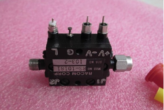
The microwave RF switch is based on the labview software platform and is provided by the computer for voltage control signals. The control signal is a digital signal and can only provide high and low levels, the high voltage is 5v, and the low voltage is 0v. Therefore, voltage conversion is needed to provide the switching circuit. The entire circuit consists of two parts: the voltage conversion circuit and the RF switching circuit. Finally, when the labview provides 5v voltage, the voltage input to the switch is 10v and 0v; when the labview provides 0v voltage, the voltage input to the switch is 0v and 10v.

Usually there are many input and output ports in the rf system. It is expensive to analyze scattering characteristics with a multi-port network analyzer. So generally use the switch to switch the signal of multiple inputs and multiple outputs, and then use a relatively simple two-port network analyzer for analysis and measurement. In the nuclear magnetic resonance system, the number of channels of the general receiving system is smaller than the number of antenna coils, so the multiple coils should also be applied with switches for switching selection. In the current general design, a ready-made switching chip is used to implement the switching function. However, most switch chips have poor reliability, are easily damaged, and the power supply lines are also more complicated. For example, although the sw-437 chip can perform a simple switching function, it has a very high anti-static requirement, and the conditions in general labs and production plants are difficult to meet the requirements of manufacturers, so practical applications are inconvenient and easily damaged. In this design, a new type of RF switch switching circuit using pin diodes is designed. The function is to select any 2-way rf signal output from 4 rf input signals.
Voltage conversion circuitBased on the labview platform, the voltage control signal provided by the computer to the RF switch is a digital signal, with an extremely high level of 5v and a low level of 0v. The voltage control signal required by the RF switch is 10v, so 5v needs to be converted to 10v. 1 is the conversion circuit diagram. When the input signal input1 is 5v, q3 is turned on, q5 is turned off, and q1 is turned on, so output1 is 0v. At this time q4 cuts off, q6 turns on, q2 ends, output2 outputs vcc is 10v. In the end, when the labview provides 5V voltage, the voltage input to the switch is 10v and 0v; when the input signal input1 is 0v, q3 is turned off, q5 is turned on, and q1 is turned off, so the output1 is 10v. At this time, q4 is on, q6 is off, q2 is on, output2 is 0v, and the voltage input to the switch is 0v and 10v. Meet the microwave RF switch operating voltage.
Performance and advantages 1) Due to the rationality and symmetry of the design, a very low transmission loss within a certain bandwidth (120mhz) is guaranteed, as shown in Figure 5 (s21). Which s21 represents: For a microwave network, when the other ports are matched, that is, when the 50r resistance is matched, the measured two-port transmission has its physical formula: s21=uout/uin. The curve maintains a very low transmission loss of approximately -0.29 db at a center frequency of 63.6 mhz and a bandwidth of 120 mhz, and the performance is stable over the entire bandwidth.
2) The alternating current of the inductor and the DC blocking effect of the capacitor ensure good matching of the input and output ports and a good reflection coefficient, as shown in Fig. 5(s11, s22)), at the center frequency of 63.6mhz. The coefficient can reach about -30db. The size of the center frequency is determined by the size of the b0 field of the nuclear magnetic resonance. For the 1.5 t system resonance frequency is 63.6 mhz.
3) Guaranteed good isolation, as shown in Figure 6, with isolation at the center frequency below -30 db.
4) In practical applications, one of the most important performance and indicators for electronic components with high frequency of use is that the requirements for the application environment are not too harsh, reliability is good, and damage is not easy. In this design, due to the use of pin-diodes, the reliability of the circuit can be significantly improved, which overcomes the disadvantages of the prior switch chip being easily damaged and having poor reliability.
Due to the rationality of the design, the microwave RF switch parameters (reflection coefficient, transmission coefficient, isolation) are ideal. This design is highly modular, making it easy to detect circuit faults. In addition, the design application is flexible, and 4 inputs and 2 outputs can use certain combinational logic to obtain the desired input and output combinations. In the NMR system, 16 input 2 output is widely used.
2500 Puffs Disposable ecig have a completely enclosed design, reducing the need for charging and replacing cartridges. The no-charge design also reduces the occurrence of faults. It is understood that with rechargeable e-cigarettes, each cartridge needs to be charged at least once and the battery efficiency is extremely low, while the design of disposable ecig can solve this problem very well.
2500 Puff Disposable Vape,Disposable Mini Vape Stick,Puff Disposable Vape,Mini Puff Disposable Vape
Shenzhen E-wisdom Network Technology Co., Ltd. , https://www.healthy-cigarettes.com