Summary
By analyzing ZigBee and WiFi protocols, combined with embedded technology, a scheme for implementing dual-mode wireless gateway is proposed. With the help of ZigBee2007, custom communication transmission protocol frames, design Linux and CC2530F256 serial transmission protocol. Secondly, establish a communication model, perform protocol analysis, and implement protocol conversion. Finally, the system software was designed to verify the feasibility of the dual-mode wireless gateway.
In recent years, with the development of communication technology, the transmission of wireless information has become more and more stable and reliable, and its error correction capability and anti-interference ability have become stronger and stronger. Especially with the rapid development of the Internet of Things, wireless communication technology is increasingly favored and valued by people because of its own convenience [1].
The ZigBee protocol based on IEEE802.15.4 has the advantages of self-organization, good stability, strong anti-interference and low power consumption. It is mainly used in agriculture, industrial testing, military and medical. However, its control center is mostly PC, and it cannot adapt to special environments such as the wild. As an increasingly popular wireless communication technology, WiFi is widely used in people's production and life due to its wide coverage and no wiring. In this way, a dual-mode wireless gateway design scheme adapted to complex environments is proposed, which has good applicability and forward-looking [2].
1 system overall structure
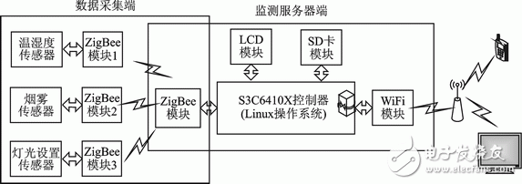
The system consists of a ZigBee module, a development board module and a WiFi module. In the ZigBee module, the Coordinator acts as the central node of the ZigBee network and is responsible for controlling and monitoring the ZigBee routing nodes. Each routing node carries a sensor responsible for transmitting the data collected by the sensor to the Coordinator. The development board module acts as a hub for protocol conversion and is used to parse the data transmitted by the Coordinator. The WiFi module encapsulates the data parsed by the development board into a WiFi frame. In this way, the conversion of the dual-mode wireless gateway is realized, and the system structure is as shown in FIG.

Figure 1 Overall structure of the system
2 Wireless gateway design
2.1 ZigBee data stream analysis
The ZB253002 module is based on TI's CC2530F256 chip and implements the ZigBee module of the ZigBee2007/PRO protocol. It has all the features of the ZigBee protocol. Its main features:
1 automatic networking. All modules are automatically networked, and the Coordinator automatically assigns addresses to all nodes. It does not require users to manually assign addresses, network joins, responses, and other professional ZigBee networking processes [3].
2 simple data transmission. The ZB253002 module can be understood as a "wireless RS232 connection" that allows data to be transferred between any node via the serial port. The ZigBee module has two data transmission modes: transparent data transmission, as long as the first byte transmitted is not 0xFE, 0xFD or 0xFC, it automatically enters the data transparent transmission mode; the point-to-point data transmission mode, the data transmission format is 0xFD ( Data transfer command) + 0x0A (data length) + (target address) + (data). The 15 bytes of node information starting with 0xFE is added to the data transmitted by the coordination node to the development board, and is provided to the TI Sensor Monitor to observe the network structure.
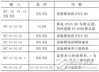
The Zigbee module setting command table is listed in Table 1.

Table 1 Zigbee module setting command table
2.2 Design of communication coordinator
The Coordinator is the center of the entire gateway transformation and wireless sensor network establishment, and is the central hub of data transmission. Therefore, the design of the Coordinator is related to the stability and reliability of the entire system. The Coordinator CC2530 uses the ZigBee2007 protocol stack. ZStack is a polling operating system provided by TI. With Z-Stack, after power-on, the Coordinator first performs hardware and network initialization, and then creates three tasks: 1ZigBee network task, which passes the Coordinator and its child nodes. "Binding" is complete. The process of binding, the coordinator establishes the network, creates the binding table, and sets the allow binding mode. The child node sends the binding request, and the Coordinator updates the binding table and responds to the child node. 2 Serial protocol parsing task, which is used to parse data from the development board and child nodes, and transfer the parsed data to the child node task or send it to the development board [4]. 3 child node task, which is mainly used to receive data returned by the child node and transmit the data to the serial protocol parsing task. In this way, the resolution of the ZigBee protocol frame is transferred to the development board, which is completed by the Linux operating system. After the Linux analysis is completed, the valid data is put into the specified shared memory. When the BOA receives the external web request, the corresponding CGI is called to acquire the data in the shared memory, and is transmitted to the user in the form of WiFi via the wireless network card.
2.3 Implementation of the transport protocol
This design completes the analysis of ZigBee protocol and the formation of WiFi protocol frame through Linux operating system. The main focus is on the design of Coordinator and Linux serial port transmission protocol. The serial frame transfer protocol custom frame format is as follows:

The format of the custom frame consists of a frame header, a function number, a valid data length, valid data, and an FCS check 5 part. The frame header is defined as 0x02; the function number varies depending on the type of data acquired. The definition of the frame format function code is listed in Table 2; the valid data length is used to identify the length range of the valid data to be read, and the maximum value is 255; valid data Store ZigBee protocol frames; FCS check is used for data segment verification.

Table 2 Protocol frame function code
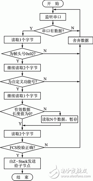
According to the custom frame format in the design, the valid data in the message is encapsulated into a fixed format and transmitted through the serial port. The development board and the Coordinator parse the received data packets by listening to the serial port data. The analysis process (taking the Coordinator as an example) is shown in Figure 2. The specific resolution process is as follows.
Step1: The Coordinator listens to the serial port (in the form of an interrupt) until the serial port has data.
Step2: Read a byte to determine whether it is a custom frame header. If not, discard the data and return to Step1.
Step3: Read two bytes and match the function code. The match failed, set the error flag, discard the data, and return to Step1.
Step4: Read a byte. If the byte data is 0, jump directly to Step6.
Step5: If the read data value is N (0 Step6: read two own data, read the data FCS check for Step1~5, if there is no error, send N bytes of valid data to the Z-Stack protocol The stack is sent to the child node by the ZStack protocol stack. Go back to Step1.
Step7: If the FCS check error, set the error flag, discard the read data, and return to Step1.

Figure 2 Serial Protocol Analysis Flowchart
Grind your beans and spices fresh without losing any flavor.
GLAREME's powerful Coffee Grinder grinders the entire bean quickly and efficiently.Instead of buying pre-ground coffee, try making coffee with fresh ground beans.It will provide a rich aroma and rich flavor, making the coffee more delicious.In addition to coffee beans, the multi-purpose grinder can also be used to chop or grind nuts, seeds, herbs and spices.The GLAREME coffee grinder is compact and stylish, adding convenience and utility to any kitchen.
Coffee Grinder
Coffee Grinder,Espresso Grinder,Coffee Bean Grinder,Commercial Coffee Grinder
Jiangmen Taifai Technology Co.,Ltd , https://www.glaremecn.com