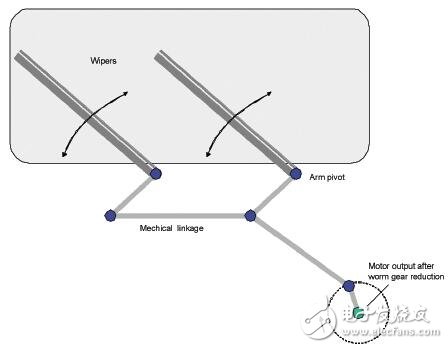
In the existing front double wiper system, the synchronization between the left and right wipers is achieved by mechanical connection (Fig. 1). This is necessary because the windshield is affected by the different conditions of dirt, wind and wiper, which makes the left and right wipers different.
For many years, the automotive industry has been looking for an intelligent solution that reduces the noise and mechanical connection requirements.
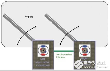
One option is to replace the mechanical connection with an electronic solution (Figure 2). In this architecture, each wiper is driven by a DC motor. The DC motor is controlled by a microcontroller and driver IC that can be mounted directly inside the motor assembly. An interface is used to handle the synchronization of the left and right wipers, so that it is not necessary to use the mechanical connection of the conventional wiper system between the two brushes, the noise is greatly reduced, and space is also saved.
For reasons of cost, the wiper system uses a DC motor. A full H-bridge gate driver that supports PWM and four power MOSFETs to control directional drive can control such motors. ICs for this application must be designed in a high voltage process and must be suitable for use in demanding environments. In addition, high-capacity DC motor applications such as windshield wiper systems should use an optimized communication interface.
Because wiper electronics are often close to car radios, EMC emissions must be controlled, and electronic breaks in car radios can be unbearable for car drivers. Differential serial communication interface (SCI) transceivers can be used to reduce this type of radiation and improve EMC performance. The SCI transceiver is a differential device that operates in single-ended mode for systems with only one wiper. This gate driver has the SCI function that makes it very similar to a LIN device. However, data rates are faster than standard LIN interfaces, up to 100 kbaud.
Each wiper module (Figure 3) consists of a microcontroller, a highly integrated gate driver and a DC motor. The position of the two wipers is measured by a plurality of Hall Sensors. The drive sends commands to the microcontroller via the wiper switch. The electronic equipment is installed close to the wiper motor and the space requirements are not very large.
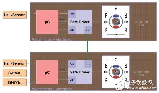
The importance of the ECU's low current consumption is growing. To ensure that the quiescent current of the IC to be used is low, a dedicated wake-up and sleep mode is used. The typical functional division of the wiper application is shown in Figure 4, consisting of a microcontroller, a microcontroller-powered voltage regulator, and other discrete components such as Hall sensors. For safety reasons, such as when driving in the rain, wiper damage can be dangerous, which requires the system to have a watchdog.
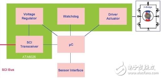
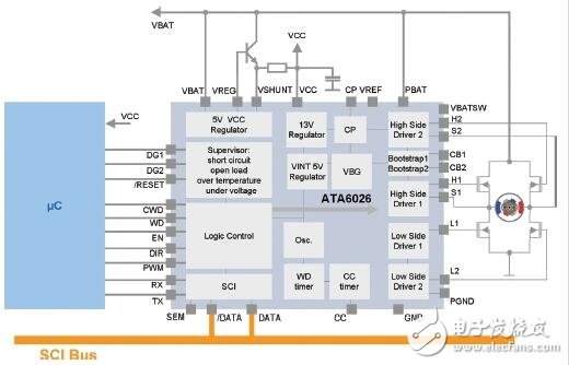
To further prevent system failure, automotive ICs are required to have many functions, such as overheat shutdown, overvoltage and undervoltage protection, and short-circuit protection, to meet stringent automotive qualification requirements (anti-conductance interference, EMC and ESD protection). To address these issues and meet the above requirements, Atmel has developed the ATA6026, a highly integrated gate driver IC. The gate driver IC includes a 5V/100mA regulator plus a watchdog for smaller designs that require a smaller PCB area, which reduces the number of external components, which is critical in electromechanical solutions. The IC is motion controlled so this feature does not require any memory to be added to the microcontroller. The function of the watchdog execution window watchdog is triggered by the microcontroller transitioning from low to high through the WD pin during window open. A reset pulse is generated if the watchdog detects a window error, ie it does not trigger when the window is open or if it is triggered incorrectly when the window is closed.
The block diagram in Figure 5 gives a schematic of the functions to be implemented and typical applications. The microcontroller controls the driving function of the IC by providing a PWM speed signal and a direction signal. Because the chip must drive the gate of the external H-bridge, it contains two push-pull drivers for controlling two external power NMOS FETs used as high-side drivers, as well as two push-pull drivers for control. Two external power NMOS FETs used as low side drivers. The driver can be used with standard or logic level power NMOS FETs. The high-side control driver uses an external bootstrap capacitor to supply the gate with a voltage greater than the battery voltage of 8V to 14V. It is also possible to control the motor in reverse. A charge pump is used to power the gate of the high-side driver, which can achieve 100% duty cycle in both directions. To prevent high peak currents in the H-bridge, switching of external power NMOS transistors is achieved using non-overlapping phases. The cross conduction time is determined by the external RC combination.
Atmel Corporation is a global industry leader in the design and manufacture of a wide range of microcontrollers, capacitive touch solutions, advanced logic, mixed-signal, non-volatile memory and radio frequency (RF) components. With one of the industry's broadest intellectual property (IP) technology portfolios, Atmel provides the electronics industry with comprehensive system solutions for the industrial, consumer, security, communications, computing and automotive markets. ATMEL's world-class expertise and experience in system-level integration enables its products to be developed on top of existing modules, ensuring minimal development delays and risks. With the industry's broadest portfolio of intellectual property (IP), Atmel offers manufacturers of complete system solutions for electronic systems. Atmel's stock code is "ATML.O" listed on the Nasdaq Stock Market. ATMEL is a world leader in the design, manufacture and marketing of advanced semiconductor products, including microprocessors, programmable logic devices, non-volatile memories, security chips, mixed-signal and RF radio integrated circuits. Through a combination of these core technologies, ATMEL produces system-level chips for a variety of general purpose and application-specific applications to meet the growing and evolving needs of today's electronic system design engineers. Through a network of production, engineering, sales and distribution in more than 60 countries, ATMEL is committed to serving customers in the electronics market in North America, Europe and Asia. Ensuring timely product introduction and ongoing customer support has made ATMEL's products the core of the latest electronics. These products in turn help end users to do more work, enjoy more convenience and maintain communication with the outside world, no matter where they are. ATMEL helps customers design smaller, cheaper, and more feature-rich products to lead the market. In 2016, it was announced by US chip maker Microchip Technology for $3.6 billion.
The internal and external voltage sources use low power and low dropout on-chip voltage regulators. An external transistor used as a power component helps to reduce power consumption. During standby, the device's sleep mode ensures very low quiescent current, typically 35 microamps. For a battery voltage of 6V to 9V, the regulated output is 5V ± 10%; when the battery voltage exceeds 9V, the regulated output is 5V ± 3%. To prevent damage to the external NPN tube and IC, a sense resistor is used to sense the regulator output current. In the event of an overcurrent, the regulator limits the current to a specified level. That is, if the regulator characteristics become a current regulator characteristic, the output voltage will breakdown. Even with a permanent conduction state (100% PWM, the bootstrap function does not exist), the fully integrated charge pump can still power the gate of the external power MOSFET of the high-side driver. Additionally, the gate of the external power NMOS used as a reverse battery protection can be powered by the charge pump output.
As mentioned earlier, ECU applications must have a sleep function to meet the requirements of low current consumption. In the sleep mode of the ATA6026, the pin EN or data wake-up IC can be used. Only a few modules are awake (bandgap, internal 5V regulator with 100 nF external DC blocking capacitor, input structure to detect EN pin threshold, and wake-up module for SCI receive section). The power-on default state is the active mode. In order to vary between the two modes, three steps are taken. In addition to activating/deactivating the EN pin, there is a second wake-up method implemented by using an SCI transceiver. In sleep mode, the SCI transceiver is partially activated and operates in single-ended mode. If activated with SCI, the EN pin can be held low without disturbing the active mode.
Since the regulator, motion control, watchdog and communication interface are all integrated on a single chip in a small QFN package, the total system cost can be reduced, and for almost all types of motor drive applications, no adaptation is required, and the output stage remains Plug and play flexibility. The IC contains a motion control section, except that the PWM speed signal and direction information must be provided by the microcontroller. There are two diagnostic pins that make fail-safe functionality possible.
MWM, spark plug
Jinan Guohua Green Power Equipment Co.,Ltd. , https://www.guohuagenerator.com