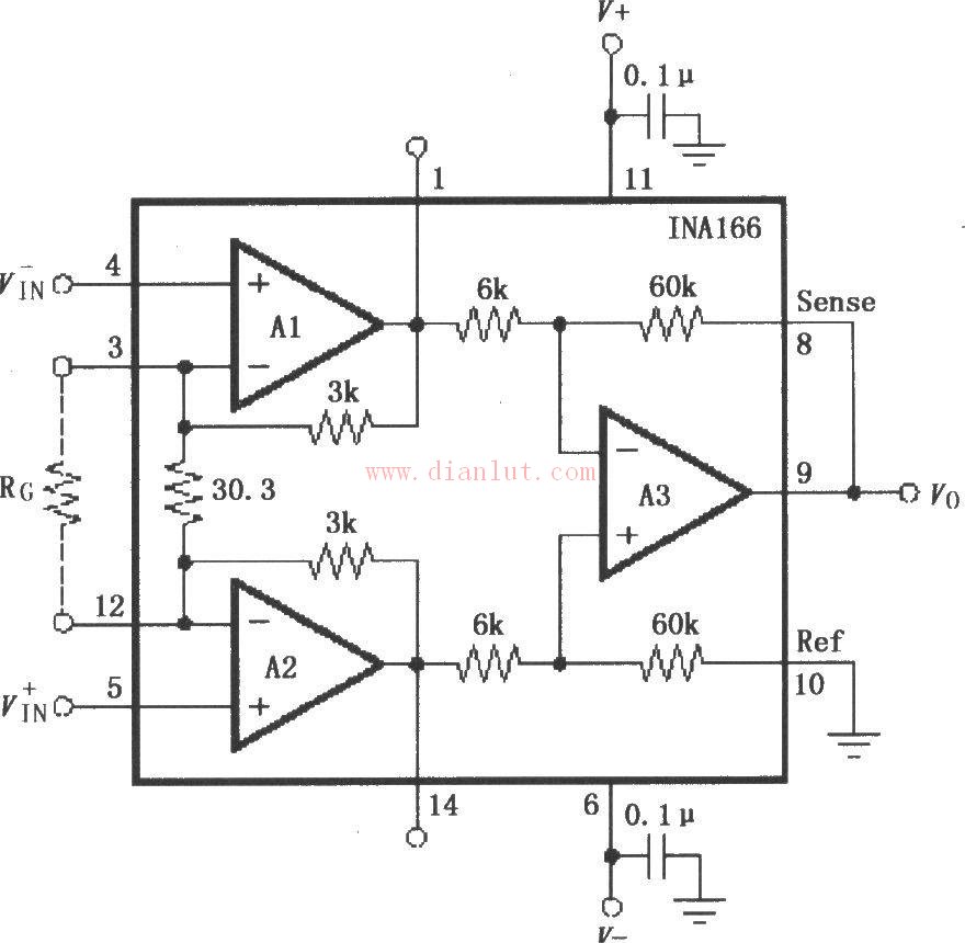
 The following is the circuit diagram of the [INA166 design signal and power supply basic connection circuit diagram]
 The figure shows the basic connection circuit for the signal and power supply of the INA166. The power supply terminal of the chip should be filtered with a 0.1μF tantalum capacitor. The PCB should be placed as close as possible to the power supply pin of the chip. The connection between the output voltage detection terminal Sense and the reference terminal Ref must be a low-resistance connection to ensure a high common-mode rejection ratio. If there is a 5Ω series resistor, the common-mode rejection ratio will decrease. The internal fixed gain is 2000, where the input stages A1, A2 have a gain of 200 and the output stage A3 has a gain of 10. Adding a gain setting resistor RG between pins 3 and 12 can change the amplifier gain with a gain of G=2000+60000/RG.

(Editor: Circuit Diagram)
3.1 Home Theater Speaker,Home Cinema System,Bluetooth Home Theatre,Home Theatre
GUANGZHOU SOWANGNY ELECTRONIC CO.,LTD , https://www.jerry-power.com