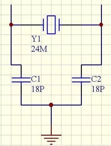
Talking about the calculation method of crystal load capacitance!

In the figure, the two capacitors of CI and C2 are called the load capacitance of the crystal oscillator. They are connected to the two pins of the crystal oscillator and the capacitance to the ground. Generally, it will affect the resonant frequency and output amplitude of the crystal oscillator in dozens of picofarads. When ordering a crystal, the supplier will ask you what the load capacitance is.
Crystal load capacitance = [(C1 * C2) / (C1 + C2)] + Cic + â–³ C
In the formula, C1 and C2 are capacitors respectively connected to the two legs of the crystal oscillator and to the ground, and the empirical value of the capacitance of the Cic integrated circuit + ΔCPCB is 3 to 5 pf. Therefore, the crystal's data sheet specifies that a 12pF payload capacitance requires 22pF 2 * 12pF = 24pF = 22pF + 2pF parasitic capacitance on each of the pins XIN and XOUT. The capacitance on both sides is C1, C2, and the load capacitance is:
Cl,Cl=cg*cd/(cg+cd)+a
That is to say, if the load capacitance is 15pf, the two sides are connected to 27pf.
The crystal oscillator pins of various logic chips can be equivalent to a capacitor three-point oscillator. The inside of the crystal oscillator pin is usually an inverter, or an odd number of inverters are connected in series. A resistor is connected between the crystal output pin XO and the crystal input pin XI. For CMOS chips, it is usually between several M and tens of MΩ. Many of the pins inside the chip already contain this resistor. No need to pick up. This resistor is used to make the inverter linear in the initial state of the oscillation. The inverter acts like an amplifier with a large gain to facilitate the start-up. The quartz crystal is also connected between the input and output of the crystal pin, equivalent to a parallel resonant circuit, and the oscillation frequency should be the parallel resonant frequency of the quartz crystal. The two capacitors next to the crystal are grounded, which is actually the voltage dividing capacitor of the capacitor three-point circuit. The grounding point is the voltage dividing point. Taking the grounding point, that is, the voltage dividing point as the reference point, the input and output of the oscillating pin are inverted, but from the two sides of the parallel resonant circuit, that is, the quartz crystal, a positive feedback is formed to ensure the continuous oscillation of the circuit. In the chip design, these two capacitors have already been formed. Generally, the two capacitors have the same capacity. The size varies depending on the process and the layout, but it is relatively small and may not be suitable for a wide frequency range. The external connection is approximately PF to tens of PF, depending on the frequency and characteristics of the quartz crystal. It should be noted that the values ​​of the two capacitors in series are connected in parallel to the resonant tank, which will affect the oscillation frequency. When the two capacitances are equal, the feedback coefficient is 0.5, which generally satisfies the oscillation condition. However, if it is not easy to start or the oscillation is unstable, the capacitance of the input terminal to the ground can be reduced, and the value of the output terminal can be increased to increase the feedback amount. There will be instructions on the data sheet of the general chip.
Finally, in a few simple places to pay attention:
1. Matching Capacitor ----- Load Capacitance refers to the capacitance required for the crystal oscillator to oscillate normally. Generally, the external capacitor is used to make the equivalent capacitance at both ends of the crystal oscillator equal to or close to the load capacitance. In the case of high requirements, the capacitance to ground of the ic input should also be considered. Generally, the capacitance connected to both ends of the crystal is twice the required load capacitance. This is close to the load capacitance.
2. Load capacitance refers to the total external effective capacitance across the crystal in the circuit. He is a test condition and a use condition. When applied, it is generally adjusted to give a precise frequency near the given load capacitance value. The size of this capacitor primarily affects the load resonant frequency and the equivalent load resonant resistance.
3. Under normal circumstances, increasing the load capacitance will reduce the oscillation frequency, while reducing the load capacitance will increase the oscillation frequency.
4. Load capacitance refers to the sum of all the effective capacitances inside and outside the IC block connected to the two leads of the crystal oscillator. It can be regarded as the serial connection capacitor of the crystal oscillator in the circuit. The different load frequencies determine the oscillation frequency of the oscillator. The crystal load capacitances with the same nominal frequency are not necessarily the same. Because the quartz crystal oscillator has two resonant frequencies, one is a low-loaded capacitive crystal with a series oscillating crystal and the other is a high-loaded capacitive crystal with a parallel oscillating crystal. Therefore, when the crystal oscillators with the same nominal frequency are interchanged, the load capacitance must be required to be one and cannot be exchanged. Otherwise, the electrical equipment will not work properly.
Screen Guard,Ultra-Thin Screen Protector,Full Coverage Screen Protector,TPU Hydrogel Screen Protector,TPU Film,Screen Protection Film
Shenzhen Jianjiantong Technology Co., Ltd. , https://www.jjthydrogelmachine.com