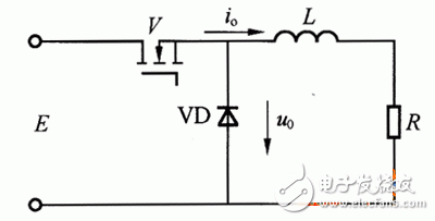
The contents of the DC chopper circuit experiment include two basic chopper circuits: a step-down chopper circuit and a boost chopper circuit. Figure 1 shows the schematic of a step-down chopper circuit.
The basic principle of the step-down chopper circuit is: during the on-time of the switch V, the power supply F supplies power to the load, the load voltage uo=E, and the load current rises exponentially; during the V-off period, the load current continues to flow through the diode VD. The load voltage 1/0 is approximately 0, and the load current decreases exponentially. In order to make the load current continuous and the pulsation small, the inductance L value of the series connection is generally large, and the average value of the load voltage is:


Figure 1 Schematic diagram of the step-down chopper circuit
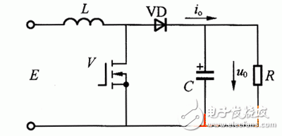
Figure 2 shows the schematic of the boost chopper circuit. When analyzing the working principle of the boost chopper circuit, first assume that the inductance L value in the circuit is large, and the capacitance C value is also large. During the V state, the power source E charges the inductor L. The charging current is basically constant at I1, and the voltage on the capacitor C supplies power to the load R. Since the C value is large, the output voltage uo is kept constant, which is recorded as Uo.

Figure 2 Schematic diagram of the boost chopper
Let V be in the on state for ton, at which point the energy accumulated on inductor L is EI1ton. When V is in the off state, E and L together charge capacitor C and provide energy to load R. Let V be in the off state for toff, and during this period, the inductor L releases the 308 PIC microcontroller application development. The typical module puts the energy (UO-E)I1toff°. When the circuit works in steady state, the inductor in one cycle T The energy accumulated by L is equal to the energy released, ie:

The output voltage of the boost chopper circuit is higher than the supply voltage.
The function that the control circuit needs to implement is to generate the PWM signal. The PWM module of PIC16F877 is used to generate the signal for controlling the on/off of the main power device in the chopper circuit. By adjusting the duty ratio α, the purpose of controlling the output voltage is achieved. . In addition, the control circuit also performs certain protection functions.
Bidirectional Dc Power Supply,Dc Ac Power Supply,Power Grid Simulator,State Grid Simulator
Jinan Xinyuhua Energy Technology Co.,Ltd , https://www.xyhenergy.com