The underwater autonomous vehicle is a general term for movable underwater detection and underwater engineering equipment, and is an important tool for marine exploration and development. It can perform tasks such as underwater terrain exploration, detection, and underwater hazardous environment operations. Its controller is an important part of its hardware. Its main function is to control part or all of the motion parameters according to its mission, to make it sail according to the specified trajectory, and to ensure the stability of AUV motion and meet the dynamic accuracy of AUV. Requirements, its performance directly affects the overall performance of the AUV. With the development of AUV technology, the controller has put forward requirements such as high reliability, high real-time, precise positioning, precise control and simple maintenance. This paper proposes a design scheme of a distributed underwater vehicle controller based on bus. The main purpose is to realize the control node design based on the overall structure of the distributed control system. In turn, a truly distributed control system is realized, which reduces the computational load of the central processing unit, and completes a large amount of data processing and analysis on site. The controller designed by the scheme has perfect intelligent control and communication functions. Compared with other bus protocols, the selected hardware and software technology is mature, safe and reliable, fast in transmission speed, low in cost, easy to expand and maintain.
1 controller structure
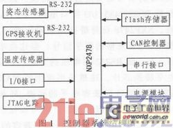
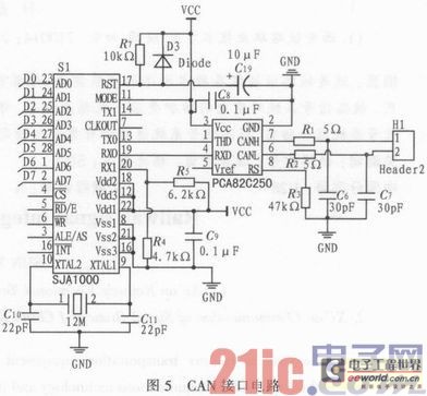
The underwater vehicle controller is composed of an MCU minimum system (JTAG circuit, reset circuit), an external expansion flash memory module, an I/O interface, an isolation circuit module, and a communication circuit. Its system structure is shown in Figure 1. The entire controller contains 4 major parts. The first is the MCU minimum control system, including the reset circuit and JTAG debug circuit. The second is the data acquisition part. The I/O interface and the RS2 32 serial interface are used to connect with various underwater sensors, collect real-time data sent by the sensor, and transmit it to the MCU for analysis and fusion. Some sensors send analog signals, and they are converted to the processing center using the AD/DA converter module. The data acquisition section also includes a temperature data collection circuit that is used to monitor the operating status of the system. The third is the data storage module, which is mainly used to store and output experimental data. The navigation data is recorded during the operation of the underwater vehicle and can also be used for commissioning purposes. The fourth is the communication part, which mainly includes the CAN bus interface circuit, which is used for transmitting data and other control commands of the controlled process to and from other nodes.

2 MCU minimum control system
The NXP2478 embedded microcontroller based on ARM7-TDMI architecture is used as the main control computer. The NXP2478 is based on ARM7 and includes a 10/100 Ethernet Media Access Controller (MAC), a USB full-speed device with 4 kB terminal RAM/host/OTG controller, 4 UARTs, two CAN channels, and 1 SPI interface, two synchronous serial ports, three I2C interfaces and one I2S interface. It also comes with a 4 MHz on-chip oscillator, 98 kB RAM, and an external memory controller to support the various serial communication interfaces described above. The smallest system based on NXP2478 mainly includes power supply module, reset circuit and JTAG module. The power module realizes two functions: 1) Voltage conversion function, reducing the input voltage of 5 V level to 3.3 V working voltage of NXP 2478 . 2) Stabilizing current function, the microcontroller needs a stable voltage with relatively small ripple voltage. If the voltage suddenly drops, it will cause the program to run away. Therefore, a special circuit must be used to stabilize the working voltage. The operating voltage is generally stabilized by connecting large resistors in parallel. The reset circuit can be implemented using a reset chip with its own watchdog function. Mainly implement power-on reset, power-down reset, manual reset and other functions. The watchdog circuit provides automatic reset protection when the program is running away. The JTAG circuit mainly implements the online simulation and programming of the program. Its circuit is shown in Figure 2.

3 data acquisition circuit
Data collection refers to the process of obtaining field information from sensors. The main components used in the underwater vehicle controller are GPS, MTI attitude sensor, depth and other sensors. The standard of sensor output signals is mostly RS232/485 standard. Some sensors require digital to analog conversion. Therefore, the data acquisition circuit mainly includes RS232/485, I/O interface circuit, AD/DA conversion circuit and isolation circuit. The NXP2478 itself has four serial ports, one of which is a 9-wire port with a full handshake signal. However, these ports operate from 0 to 3.3 V. The RS232 voltage is about ±12 V, so a level shifting chip is needed. The commonly used MAX232 chip is used here. The I/O interface circuit also needs to be compatible level conversion. The external switch signal may have a relatively large voltage amplitude. The isolation chip can protect the influence of external signal crosstalk on the controller and play a level compatible function. The I/O isolation module is shown in Figure 3.

Temperature monitoring is used as part of the data acquisition to detect the temperature status of the controller while it is running and to provide an alarm function. This article uses DS18B20 as the temperature data sensor. DS18B 20 is a temperature sensor that directly outputs digital signals widely used in distributed temperature control systems. The output data complies with the one-wire bus protocol. The acquisition temperature ranges from -55 degrees Celsius to 125 degrees Celsius, and the output digital signal can be directly entered into the MCU's I/O port. The DS18B20 has only three signal lines: ground, power and data. Therefore, the interface circuit is very simple, and the data line can be directly connected to the GPIO port of the MCU.
Car Super Tweeter,Audio Car Tweeter,Car Tweeter Speakers,Audio Multimedia Driver
NINGBO BOILINGSOUND ELECTRONICS CO.,LTD , https://www.tweeterspeaker.com