Overview
Both mechanical potentiometers and digital potentiometers have indeterminate end-to-end tolerances. Maxim's digital potentiometers typically have end-to-end resistance errors of 20% to 30%. When digital potentiometers are connected in series with other resistors to form a voltage divider network The deviation of this resistance may cause some problems, causing the amount of voltage change to exceed the allowable error range.
Discusses how to eliminate voltage variations when using digital potentiometers in series with other resistors to form a voltage divider network. A proportional circuit design method is discussed to convert the resistance deviation into an acceptable current variation, which can effectively eliminate the voltage variation. In the circuit given here, the voltage output depends on the ratio of the potentiometer, and the temperature coefficient can be well controlled in the design.
Proportional circuit design
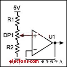
The immediate problem with this design is that a 3% error can cause the voltage to vary between 3V and 4.5V. Using the block diagram shown in Figure 1, basic calculations can be performed. The digital potentiometer is 50kΩ (25% tolerance), R1 is 16.5K (1%), and R2 is 100K (1%). The 25% tolerance of the potentiometer's end-to-end resistance is the largest source of error in the design.

Figure 1. Basic block diagram
Now consider the same calculation with different tap resistors. If the potentiometer is 37.5kΩ, the top voltage is 4.46V and the low end is 3.25V. If the potentiometer is 62.5kΩ, the top voltage is 4.54V and the low voltage is 2.79V. In this circuit, due to the large end-to-end resistance deviation of the potentiometer, this basic architecture cannot be used to solve the voltage variation problem.
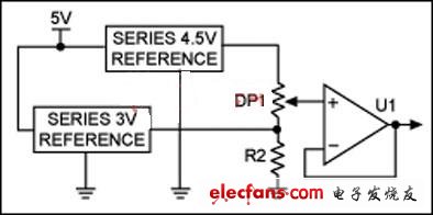
The circuit of Figure 2 simply uses the resistance ratio of the potentiometer to divide the voltage.

Figure 2. Substituting a design with two voltage references
Two voltage references are introduced into the circuit to control the error and temperature coefficient. The absolute end-to-end deviation of the digital potentiometer changes the loop current, but does not affect the voltage. The output voltage varies proportionally, depending only on the resistance ratio of the potentiometer tap position.
Both references control the output voltage through feedback, and R2 (25K to 50K) determines the source current of the two references. Bypass capacitors are discussed in the MAXIM digital potentiometer data sheet, which increases the capacitance depending on the layout.
Fire alarm cable
Rated Voltage: 300V/500V
Conductor: Class 1 or Class 2 copper
Insulation: Fire Retardant PVC
Shield: Aluminum Foil&Tinned Copper or N/A
Sheath: Fire Retardant PVC
Application: Those Fire Cable are used in high rise buildings,schools and educational institutions, hospitals, etc. for the connection with security systems like smoke detectors, emergency lighting, exit signboards and fire command center.
Fire Alarm Cable,Fireproof Cable,Fire Resistant Cable Types,Fireproof Wire
Shenzhen Bendakang Cables Holding Co., Ltd , https://www.bdkcables.com