Abstract: In order to solve the problem of low efficiency and short transmission distance of a multi-to-one (multiple transmit (TX) coils to a receiving (RX) coil) magnetic resonance coupling (CMR) wireless energy transmission system, a two-to-one (two TX coil to a RX coil) CMR wireless energy transmission system adaptive impedance matching method. The principle of this method is that when the internal resistance of the signal source is equal to the load impedance, the energy will be transmitted to the load without loss, but it is usually not matched. Therefore, an LC impedance matching network (IMN) must be introduced to make the internal resistance of the source and The load end impedance is equal. Because the change of the RX coil's spatial position will cause the input impedance of the transmitter to change, different LC impedance matching networks are set for different RX coil positions, so that it can achieve the purpose of adaptive impedance matching. Finally, an experiment was carried out. With the change of the RX coil's position in space, the impedance matching network can quickly realize automatic matching, and the energy transmission efficiency can reach up to 87%, and the charging distance for the mobile phone has been increased to more than 10cm.
0 Preface
Due to the shortcomings of wired charging that are not easy to carry, and the damage of the connector will cause the risk of electric shock, the use of wireless charging to achieve efficient energy transmission has become a trend [1]. At present, the wireless charging method based on magnetic resonance can realize long-distance energy transmission. The main principle is to create a changing magnetic field in the transmitting coil, and the receiving coil converts the changing magnetic field into electric current to complete the energy transmission process. Magnetic resonance wireless energy transmission has the advantages of long transmission distance, high efficiency, and convenient use. It has become the mainstream research direction of wireless power transmission [2-3]. However, there are many unresolved problems in the magnetic resonance wireless energy transmission system, and impedance matching is one of them [4-5]. The movement of the RX coil usually brings about a large input impedance change. When the input impedance does not match the internal equivalent impedance of the power amplifier, part of the energy will be reflected back, reducing the energy transmission efficiency [6-7]. There have been many documents discussing how to solve the impedance mismatch problem, but most of them only focus on 1-to-1 systems. The performance, efficiency analysis, and design methods of the 1-to-1 system have been extensively studied from various aspects [8]. In fact, the CMR system does not necessarily have only one TX coil. In many cases, multiple TX coils are used [9]. For example, some research groups use beamforming algorithms to beam spatial magnetic fields to increase the transmission distance, which usually requires multiple TX coils [10].
This article first discusses the impedance matching method of the 1 to 1 CMR system, then studies the 2 to 1 CMR system, analyzes the similarities and differences between them, and further discusses in theory how to design the IMN of the 2 to 1 CMR system and the adaptive impedance matching process method. It is verified by a large number of experiments that the method is effective, the transmission efficiency of the two TX coils are improved, and the system can adapt to the spatial movement of the mobile receiving end.
1 Theoretical Derivation
1.1 Equivalent circuit model of a TX coil and an RX coil
The CMR system equivalent circuit of a TX coil and an RX coil is shown in Figure 1.
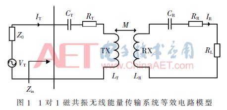
The power supply can be represented by an equivalent internal resistance Z0 (usually 50Ω) and a voltage source VS with amplitude. RL and RR are the parasitic resistances of the TX and RX coils. The current in the TX coil is IT, and the current in the RX coil is IR. From Kirchhoff's voltage law (KVL), we get:

Among them, M represents the mutual inductance between the transmitting and receiving coils, RL is the load, CT and CR are the resonant capacitances of the transmitting and receiving coils respectively, combining equations (1) and (2), when the system is working at the resonance frequency, jwLT +1/(jwCT) and jwLR+1/(jwCR) will cancel each other, and the expression Zin of the input impedance of the TX coil can be obtained:

Among them, M represents the coupling coefficient between the RX and TX coils, which changes with the relative position between RX and TX. When M changes, it causes the input impedance Zin to change and does not match the internal impedance Z0 of the power supply. The power will be reflected when it reaches the load, thereby reducing the power transmission efficiency.
1.2 The impedance matching method of a TX coil and an RX coil
Common IMN has three types: L-type, π-type and T-type [11]. If there is no special requirement for the system frequency band or Q value, generally choose the L-type IMN with fewer components. Figure 2(a) is an equivalent circuit with added impedance matching, Figure 2(b) is an L-type impedance matching network structure, and Figure 2(c) is an inverse L-type impedance matching network structure.

Assuming that the power supply impedance and the input impedance of the transmitter are respectively expressed as Z0=R0+jX0 and Zin=Rin+jXin. When Rin>R0, use L-type IMN; when Rin
1.3 Equivalent circuit model of two TX coils and one Rx coil
With two TX coils, impedance matching analysis becomes more complicated because of mutual inductance between the two TX coils. The 2 to 1 CMR system is shown in Figure 3.
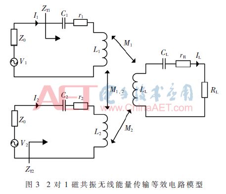
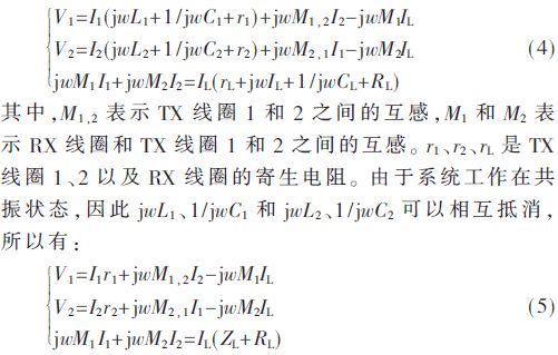
Assuming that the currents flowing through the two TX coils are I1 and I2, applying KVL can get:
From equation (5), the input impedances of transmitting coil 1 and transmitting coil 2 are:
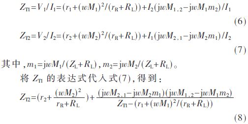
It can be seen from formula (6) that ZT1 contains two parts: r1+(wM1)2/(rR+RL) and I2(jwM1,2-jwM1m2)/I1, where r1+(wM1)2/(rR+RL) means The effect of RX on TX1 is similar to the expression in equation (3), which is the same as a 1-to-1 CMR system. They both indicate the reflection impedance of the RX coil on the TX coil. On the contrary, I1(jwM2, 1-jwM2m1)/I2 represents the effect of TX2 on TX1, which does not exist in a 1 to 1 CMR system. This is the basic difference between a 1 to 1 CMR system and a 2 to 1 CMR system. From equations (6) and (7), it can be seen that changes in I1 will lead to changes in ZT2, and changes in I2 will lead to changes in ZT1. Based on this fact, when designing the IMN of a 2-to-1 CMR system, M1, 2 must be considered.
1.4 Impedance matching method of two TX coils and one RX coil
The movement of the receiving end in space will cause ZT1 and ZT2 to change, but the degree of change of ZT1 and ZT2 is different, which is jointly determined by the mutual inductance between the RX coil and the TX coil and the two TX coils. Under normal circumstances, TX coil 1 and TX coil 2 are placed horizontally on a non-metallic table and have a certain distance between them. This distance determines the mutual inductance M1,2 between TX coil 1 and TX coil 2. Generally, the spatial location can be divided into three areas: A, B and C areas, A is the space above TX coil 1, area C is the space above TX coil 2, and area B is the space between TX coils 1 and 2. Figure 4 shows the spatial distribution of RX coils.
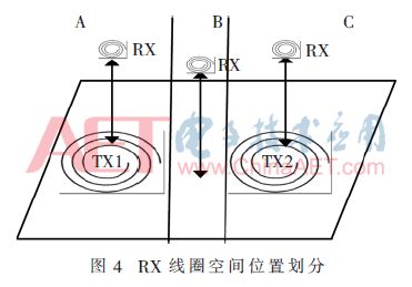
When the RX coil is in the A zone, since it is closer to the TX coil 1, M1>M2. It can be seen from formula (6) that if the value of rR+RL is determined, the value of ZT1 can be significantly improved, while the value of ZT2 has a smaller change. Similarly, when the RX coil is in the C area, since it is closer to the TX coil 2, M1
When the RX coil is in zone B, it can be considered that it is evenly close to TX coils 1 and 2 and has the same effect on TX coils 1 and 2.
1.4.1 RT1>Z0 and RT2>Z0
When RT1>Z0 and RT2>Z0, L-type IMN is applied to TX1 and TX2. Figure 5 shows the proposed circuit diagram.
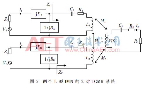
In order to achieve impedance matching, the following conditions must be met at the same time:
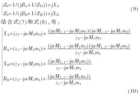
XA, BA, XB and BB can be calculated from equation (10), where XA and XB are the total inductive reactance value of IMN, BA and BB are the total capacitive reactance value of IMN, and then the equation X=wL and B= wC can get the required inductance and capacitance values ​​in IMN.
1.4.2RT1
When RT1
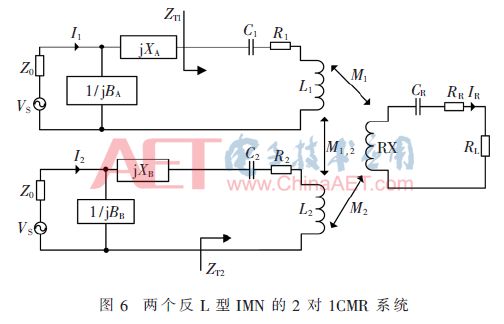
In order to achieve impedance matching, the following conditions must be met at the same time:
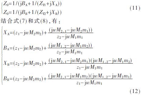
From this, the required inductance and capacitance values ​​of the IMN can be calculated.
1.4.3 RT1>Z0 and RT2Z0
This situation usually occurs when the receiving end is spatially close to one TX coil and away from the other TX coil, and only discusses the situation where the receiving end is spatially close to TX1 and away from TX2. In this case, TX1 should use L-shaped IMN, and TX2 should use reverse L-shaped IMN. Figure 7 shows the proposed circuit diagram.
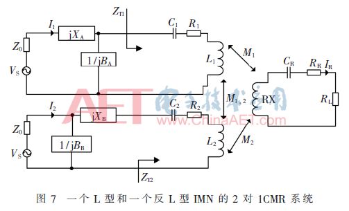
In order to achieve impedance matching, the following conditions must be met at the same time:
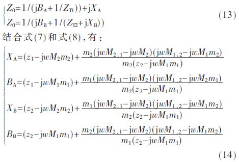
From this, the required inductance and capacitance values ​​of the IMN can be calculated.
2 Impedance matching process
The system block diagram is shown as in Fig. 8.
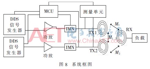
Build the system shown in Figure 8 to measure M1,2. The automatic impedance matching network will be divided into the following steps:
(1) Before impedance matching, TX1 and TX2 must be fixed first, and the mutual inductance M1, 2 between them must be measured with a vector network analyzer;
(2) Without IMN, disconnect TX2 and TX1 respectively, and the AD8302 of the MCU controls the measurement unit to read the amplitude and phase ratio between the incident wave and the reflected wave, measure the mutual inductance M1 between RX and TX1, measure the difference between RX and TX2 The mutual inductance between M2;
(3) MCU will record the relevant parameters, and then determine the IMN type based on this and calculate the values ​​of XA, BA, XB and BB;
(4) L-type and reverse-L-type IMN are composed of capacitor and inductor arrays. After completing step (3), determine the IMN type, and calculate each capacitor array and pole by the equations X=wL and B=wC The value of the array and other components;
(5) After waiting for Ts, repeat the above steps to achieve the purpose of adaptive impedance matching.
3 experiments
In order to verify the proposed adaptive IMN design method for the 2-pair-1 CMR system, a large number of experiments were carried out. In the case of low frequency, the energy transmission efficiency is low. The resonance frequency set in this experiment is 6.78MHz, and the structure of the experimental device is shown in Figure 9.
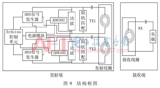
The experiment consists of 5 modules: DDS signal generator, measurement unit (AD8302), Arduino control unit (MCU), power amplifier, impedance matching network. The two sets of impedance matching networks are connected to TX1 and TX2 respectively. The receiving module includes: RX coil and its series resonant capacitor, and a 5Ω power resistor. The experimental parameter settings are shown in Table 1.

3.1 Receiving coil position
When the relative positions of TX1 and TX2 are fixed, place RX in different spatial positions, as shown in Figure 10.
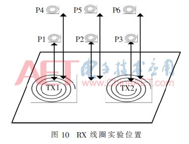
This article tries to choose some special spatial locations for experimentation. Choose two positions in each area, TX1 and TX2 are placed horizontally on the wooden table, there is a 3cm gap between them. P1 and P4 are located above TX1 (area A), aligned with its center axis; P3 and P6 are located above TX2 (area C), aligned with its center axis; P2 and P5 are located on the center between TX1 and TX2. The height of P1, P2 and P3 is 2cm, and the height of P4, P5 and P6 is 5cm.
3.2 Efficiency analysis
Record the efficiency of TX1 and TX2, as shown in Table 2.
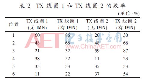
It can be seen from Table 2 that the power transmission efficiency of TX1 and TX2 are enhanced at all selected positions. This is because when the IMN is used, the overall input impedance of the transmitter is close to 50Ω. When the energy reaches the load, the energy will not be reflected back, but will enter the IMN and TX coils. Since IMN only uses inductors or capacitors, if they are ideal components, they will not consume any energy. In fact, capacitors are not ideal, so they will inevitably consume some energy. Figure 11 shows the efficiency of TX1 and TX2.
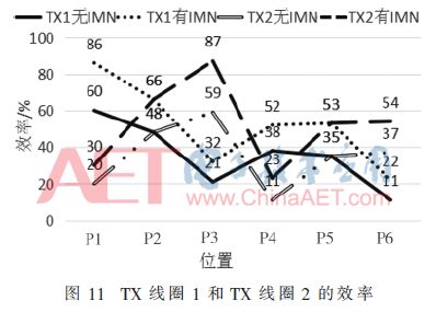
It can be seen from Figure 11 that when the adaptive IMN is introduced, the transmission efficiency of the system is significantly improved.
4 Conclusion
This paper studies the problem of adaptive impedance matching in a 2-pair-1 CMR system, proposes a method of adaptive impedance matching, and then conducts experiments to verify its effectiveness. The results show that the proposed adaptive impedance matching scheme can effectively solve the impedance mismatch problem caused when the receiving coil moves in space, improve the energy transmission efficiency, and the maximum transmission efficiency reaches 87%. At the same time, the charging distance for the mobile phone and the bulb is increased to 10cm and above 15cm.
Cement resistance: is the resistance wire wound on the alkali heat-resistant porcelain, coupled with heat resistant, resistant to wet outside fixed protection and corrosion resistance of the materials and the winding resistance into the square porcelain box body, using special incombustible cement packing seal.The outside of cement resistance is mainly made of ceramic materials (generally divided into high alumina porcelain and feldspar porcelain).
Cement Resistor,Thermal Cement Resistor,Thin Film Cement Resistor,Winding Cement Resistor,Fusing Cement Resistor
YANGZHOU POSITIONING TECH CO., LTD , https://www.yzpstcc.com