Are you feeling uncomfortable when compensating for the feedback loop of an isolated power supply? When you make a measurement, the disconnection position of the loop will directly affect the difficulty of this work.
When selecting a compensation component around the TL431 circuit, it is critical to disconnect the loop at a specific location. We can choose to break the loop in two places.
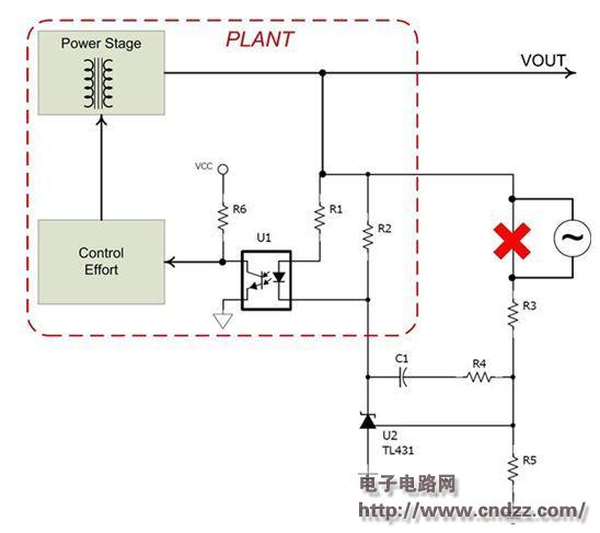
Most engineers prefer to break the loop at the position of the feedback resistor divider shown in Figure 1. After all, we do this in non-isolated buck circuits. When we do the same in this isolated power supply, the internal loop becomes part of the power plant equipment and complicates the equations and design process. When we break the loop on the voltage divider, we must:
1. Check the stability of the internal open circuit.
2. Then we have to look at the closed loop response of this internal loop. The closed internal circuit is a power plant device that is controlled by an external circuit.
3. Ensure stability by selecting the compensation components around the TL431 in the external loop. 
Figure 1. Disconnecting the loop at the position of the feedback divider can complicate the measurement process.
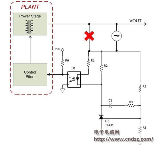
By breaking the loop in the manner shown in Figure 2, we can stabilize the power supply in a simple step. Power plant equipment is now defined as the transfer function of the optocoupler's output to the power supply output, while the two loops are included in the compensation, not in the power plant. This allows us to use power tips: compensate for the simple equations described in the isolated power supply to quickly select the compensation components around the TL431. 
Figure 2. Disconnecting the loop between the output and the entire TL431 circuit simplifies the measurement process.
Frequently, a 50 ohm resistor is included in the circuit, the sole purpose of which is to provide a place to insert interference while measuring the loop. When placed in the position marked in Figure 2, the impedance of this resistor will affect the performance of the power supply. The optocoupler current must flow through this resistor and cause a voltage regulation error. If you place a resistor in this position, you must use a 0 ohm resistor. When performing loop measurements, a 50 ohm resistor can be temporarily placed to insert interference. After that, the 0 ohm resistor must be replaced.
There are a large number of isolated power supplies in our reference design Power Lab library. Here are some examples of a 0 ohm placeholder resistor used to measure the feedback loop at the position shown in Figure 2:
• PMP9203 – Universal AC Input 5V/2A USB Adapter Reference Design for Constant Frequency Operation • PMP9204 – Universal AC Input 5V/2A USB Adapter Reference Design with DCM/Valley Switch and Optical Feedback • PMP9720 – 48V-60Vdc Input, 12V/150W Active Clamp Forward - Reference Design
custom cnc milling parts aluminum,cnc milling parts,cnc machining parts aluminum
Dongguan Yingxin Technology Co., Ltd. , https://www.dgyingxintech.com