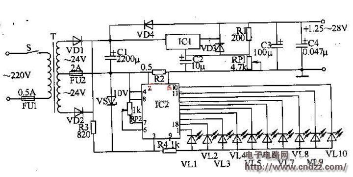
This example introduces an adjustable DC regulated power supply circuit with a current indication made of LEDs. The output power is 50W and the output voltage range is 1.25-28V.
Circuit Operation Principle The adjustable DC stabilized power supply circuit consists of a power input circuit, a regulated output circuit, and a current indicating circuit, as shown in the figure. 
The power input circuit is composed of a power switch fuse fuse FU1, FU2, a power transformer T, rectifier diodes VD1, VD2, and a filter capacitor Cl.
The regulated output circuit is composed of a three-terminal adjustable voltage regulator integrated circuit ICl, a capacitor C2, a C4, a diode VD3, a VD4, a resistor Rl and a potentiometer RPl.
The current indicating circuit is composed of a resistor R2. R4, Zener diode VS, LED driver integrated circuit IC2 and LED VLl, VLlO.
After the power switch S is turned on, the AC 220V voltage is divided into two by T step-down, VDl and VD2 rectification and Cl filter: one channel is regulated by ICl and RPl, and the other is VS regulated to lOV. IC2's working power supply.
R2 is a current sampling resistor. When the output current flows through R2, a voltage drop is generated on R2. This voltage signal is input from the 5 pin of IC2. After buffer amplification and comparison with the reference voltage dividing circuit, the LED VLl-VLlO is driven to emit light, indicating the current value.
Adjustable DC stabilized power supply component selection
Rl and R4 select 1/4W metal film resistor for use; R2 selects 2W wire wound resistor for use; R3 selects lW metal film resistor for use.
Both RPl and Rå¨ use linear potentiometers.
Cl-C3 selects aluminum electrolytic capacitors with a withstand voltage of 5OV; it is called monolithic capacitor.
VDl and VD2 select lN5401 or lN5404 silicon rectifier diode; VD3 and VD4 select 1N4007 silicon rectifier diode.
VS selects silicon steady voltage diode of lW, lOV.
VLl-VLlO selects φ3mm LEDs.
lCl selects LM317T type three-terminal voltage regulator integrated circuit; IC2 selects LM3914 type LED display driver integrated circuit.
T selects 5OW, the secondary voltage is a dual 24V power transformer.
After the adjustable DC stabilized power supply circuit debugging circuit is installed, power calibration is performed.
Calibration voltage: Use a multimeter to measure the output voltage, adjust RPl, and mark the corresponding voltage value on the corresponding scale of RPl.
Calibration current: Connect a 200Ω, lOW cement resistor to the output of the regulated power supply, then adjust RPl to make the output voltage lOV. Then adjust Rå¨ so that VLlO just lights up, and the corresponding scale is 5OOmA. The entire adjustable DC regulated power supply current scale can be divided or doubled by this point.
Household Appliances Aluminum Alloy Die Casting
Household Appliances Aluminum Alloy Die Casting,Case Die Casting,Case Aluminum Die Casting,Face Recognition Aluminum Alloy Frame
Dongguan Metalwork Technology Co., LTD. , https://www.diecast-pro.com