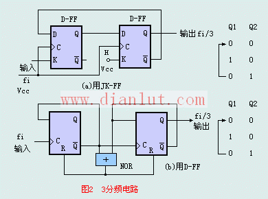
The following is a circuit diagram of [Implementing a three-way circuit with a flip-flop]
Figure 2 is a 3-way circuit. It is convenient to use the JK-FF to divide by 3, and it is possible to realize the synchronous count division without adding any logic circuit. However, when D-FF is used to divide by 3, a decoding feedback circuit must be added. As shown in the decoding reset circuit shown in Figure 2, the forced counting state returns to the initial all-zero state, that is, the NOR gate circuit is used to set Q2, Q1 = " The state decoding of 11B" generates an "H" level reset pulse, forcing FF1 and FF2 to be reset at the same time (before the arrival of the pulse of the next clock input Fi), so that Q2, Q1 = "11B" state is only instantaneous as a "glitch" There is a cycle that does not affect the frequency division. This "glitch" exists only in Q1. It may cause errors in practice. It should be added with a clock synchronization circuit or a RC low-pass filter circuit to filter out, or only Q2 is used as the output. D-FF divides by 3, and can also use the AND gate to decode Q2 and Q1 to realize returning zero.

Automotive Wiring Harness Protection Sleeve
Automotive Wiring Harness Protection Sleeve,Braided Heat Shrink Tubing,Wear Resistant Heat Shrink Tubing
Shenzhen Huiyunhai Tech.Co., Ltd. , https://www.cablesleevefactory.com