The touch mode light switch described here can be turned on and off with only one touch electrode. Like the mode light switch, the two-wire system with phase-in switch can directly replace the ordinary switch without changing the original wiring in the room.
working principle
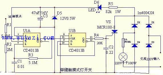
The touch switch circuit is shown in the figure. The right part of the dotted line in the figure is the ordinary power supply wiring, and the left part is the touch light switch line. The main circuit of the switch is composed of VDl-VD4 and VS, and the control circuit composed of the integrated block A and the like. R51VD5 and C3 form a simple resistor buck regulator line, and output DC power of about 12V for control loop and other power. The LED is a low light indicator and is used to indicate the position of the touch switch at night for convenient use. If you do not need low light indication, use a wire to short the positive and negative pin solder joints of the LED.
The integrated circuit A is a block double D flip-flop, which is respectively connected into a monostable circuit and a bistable circuit. The function of the monostable circuit is to pulse broaden the shape of the touch signal to ensure that each touch action is reliable. The bistable circuit is used to drive the thyristor VS on or off. M is the touch electrode piece, the finger touches M, the voltage drop of the alternating current of the human body on the resistor R2, and the positive half cycle signal enters the 3 pin of A, that is, the CP end of the monostable circuit, so that the monostable circuit is flipped into the transient state. The output terminal Q, that is, the 1 pin jumps from the original low level to the high level. This high level is charged to the Cl via R3, so that the 4 pin, that is, the R terminal potential rises, and when it rises to the reset level, the monostable state The circuit is reset and the 1 pin is restored to a low level. Therefore, each time the electrode sheet M is touched, the 1 leg outputs a positive pulse of a fixed width. This positive pulse will be directly applied to the CP terminal of the 11-pin bistable circuit, so that the bistable circuit is flipped once, and the output terminal Q, that is, the 13-pin level is changed once. When pin 13 is high, the gate of VS is turned on by R4 to obtain the forward trigger current, that is, the electronic switch is closed, and the light is illuminated. At this time, the voltage across the capacitor C3 will drop to about 3V, and the LED will go out, but A will still work normally. When the 13 pin outputs a low level, the VS loses the trigger current. When the AC power crosses zero, it turns off and the lamp goes out. At this time, the voltage across C3 can be restored to 12V, and the LED lights up as a weak light indication.
It can be seen that the action of "on" or "off" the electric lamp can be realized every time the electrode sheet M is touched. Component selection and production A CD4013 double D flip-flop digital integrated circuit, it uses 14-pin dual in-line plastic packaging package oVS using MCRl00-8 2N6565 type and other small plastic unidirectional thyristor. VD1-4 with 1N4004-1N4007 type For silicon rectifier diodes, VD5 uses 12V, 1/2W Zener diodes, such as 2CW60. LEDs can be used with red LEDs.

R5 is best to use RJ-1W metal film resistors, and the rest of the resistors use RTX-1/8W carbon film resistors. C1 C2 can use CT4 type monolithic capacitor, C3 uses CDll-16V type electrolytic capacitor. The switch housing is made of 86 series switch panel. To ensure the absolute safety of the user, a 2M high resistance resistor can be connected in series between the contact electrode and the resistor R1. The switch is connected to the lighting circuit, and the connection is the same as the ordinary switch. According to the figure, the phase line enters the switch. If the phase of the phase neutral line is reversed, the circuit will not work normally. After the circuit is installed, it does not need to be debugged, and it can work normally after power-on. Mode M, the light is on; touch again - the light is off.
Headphone speaker:
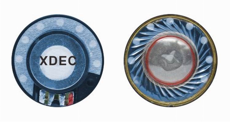
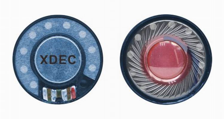
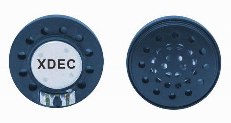
Headphone speaker is a king of speaker unit which is used for headphone, it also called headphone driver. These speakers have high sound pressure level, fast frequency response, wide frequency response range and low distortion. Headphone speakers are mainly used for voice headphone (e.g. customer service phone, call center headphone, military intercom headset- ) and music headphone (e.g. Bluetooth headphone, sport headphone, game headphone-).
Our main headphone speakers include:
1) From the diameter, we have speakers in 23mm ~ 57mm.
2) From the impedance, we have speakers of 32ohm/150ohm/300ohm/1000ohm.


FAQ
Q1. What
is the MOQ?
XDEC: 2000pcs for one model.
Q2. What is the delivery lead time?
XDEC: 15 days for normal orders, 10 days for urgent orders.
Q3. What are the payment methods?
XDEC: T/T, PayPal, Western Union, Money Gram.
Q4. Can you offer samples for testing?
XDEC: Yes, we offer free samples.
Q5. How soon can you send samples?
XDEC: We can send samples in 3-5 days.
Headphone Speaker,Headset Speaker,Earphone Speaker,Headphone Parts Speaker
Shenzhen Xuanda Electronics Co., Ltd. , https://www.xdecspeaker.com