This article will be based on the concept of DC / AC SCAN and compare them to give you a more comprehensive understanding of DC / AC SCAN test technology.
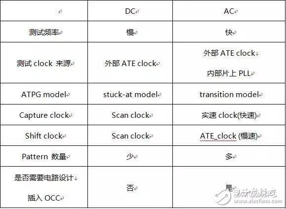
SCAN technology, also known as ATPG technology - tests std-logic. The main implementation tools are: TestKompress and Synopsys TetraMAX which use ATent to generate ATPG; DFT compiler which uses synopsys to insert scan chain. Generally speaking, DCSCAN is normal scan test. Slow test, the test frequency is 10M-30M, AC SCAN is the at-speed scan that is the real speed test, the test frequency is the same as the real working frequency of the chip.
During the period from the 1970s to 1995, since the chip's operating frequency was only 20-100M, and the scan test was only DC SCAN, we could capture all the manufacturing defects of std-logic. But since 1995, test scientists and engineers have found that chips that are not defective by DC SCAN testing can be problematic at high operating frequencies. The root cause is that as the manufacturing process moves toward deep sub-micron, the chip's operating frequency is also increased to 200M-1G. The original SCAN test methods and models can no longer capture all the manufacturing defects of std-logic. The unanimous idea of ​​everyone is - "Run, SCAN", to increase the frequency of SCAN to match the real operating frequency of the chip, and use the new TransiTIon atpg model to generate the test pattern.
Below we introduce the similarities and differences between DC SCAN and AC SCAN
Today's industrial high-speed chips are required to do DC SCAN test and AC SCAN test, so DFT engineers also need to insert two test circuits at the same time to generate two sets of test patterns.
The specific implementation process is as follows
1 Read the netlist without inserting scan
2 Insert the scan chain and OCC (on chipclocking) module using Design compiler, insert mux, fix DRC
3 EDT compression scan chain using Testcompress
4 Use Testcompress to generate test DC/ACpattern and generate test-tested Testbench
5 Verify the correctness of DC/AC patterns and the correctness of the circuit
6 Verify that the timing of the DC/ACpatterns related circuit meets the requirements using SDF
7 Convert to ATE required format using DC/AC patterns (wgl file), debug and use on ATE
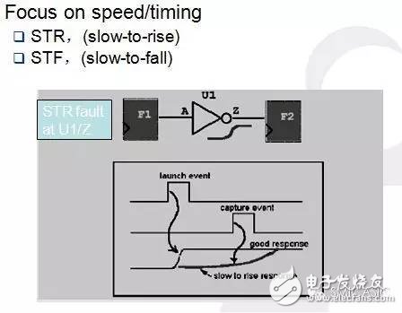
The TransiTIon faultmodel used by the ATPG tool is shown below.

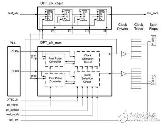
The commonly used OCC circuit structure is as follows

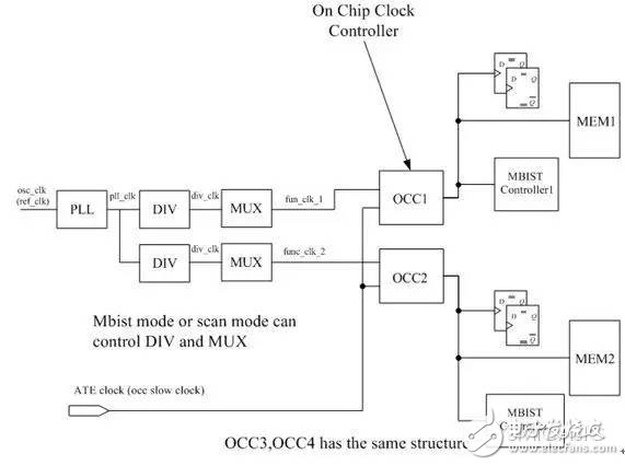
Our typical circuit after inserting OCC is as shown below.

LANA Vape E-liquids is so convenient, portable, and small volume, you can choose the flavors you like, then add into your lana vape.
We are China leading manufacturer and supplier of Disposable Vapes puff bars, lana vape e-liquids 30ml,lana vape e-liquids energy,
lana vape e liquids e-cig,lana vape e-liquids for pods, and e-cigarette kit, and we specialize in disposable vapes, e-cigarette vape pens,
e-cigarette kits, etc.
lana vape e-liquids 30ml,lana vape e-liquids energy,lana vape e liquids e-cig,lana vape e-liquids for pods,lana vape e-liquids salt nic
Ningbo Autrends International Trade Co.,Ltd. , https://www.mosvape.com