A servo motor is an engine that controls the operation of a mechanical component in a servo system, and is an auxiliary motor indirect transmission. The servo motor can control the speed and position accuracy very accurately, and can convert the voltage signal into torque and speed to drive the control object. The servo motor rotor speed is controlled by the input signal and can react quickly. It is used as an actuator in the automatic control system, and has the characteristics of small electromechanical time constant, high linearity, and starting voltage, which can receive the received electrical signal. Converted to an angular displacement or angular velocity output on the motor shaft. Divided into two major categories of DC and AC servo motor, its main feature is that when the signal voltage is zero, there is no rotation phenomenon, and the rotation speed decreases uniformly with the increase of torque.
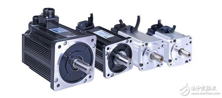
The servo motor, also known as the actuator motor, converts the input voltage signal into an angular displacement or angular velocity output of the rotating shaft. Changing the magnitude and polarity of the input signal can change the speed and steering of the servo motor. The input voltage signal is also called a control signal or Control voltage.
There are many types of servo motors and they are widely used. For example, in a radar antenna system, a radar antenna is dragged by an AC servo motor. When a radio wave emitted by an antenna encounters a target, it is reflected back to the radar receiver; the radar receiver sets the target's azimuth and distance. After the determination, an electric signal is sent to the AC servo motor, and the AC servo motor drags the radar antenna to track the target rotation according to the electric signal.
Servo motors are classified into two types: DC servo motors and AC servo motors, depending on the power source used. The DC servo motor has a large output power, and the power range is from 1 to 600 watts, and some even reach up to kilowatts. The AC servo motor has a small output power, and the power range is generally 0.1 to 100 watts.
Servo motor internal structureThe servo motor can control the speed and position accuracy very accurately, and can convert the voltage signal into torque and speed to drive the control object. The servo motor rotor speed is controlled by the input signal and can react quickly. It is used as an actuator in the automatic control system, and has the characteristics of small electromechanical time constant, high linearity, and starting voltage, which can receive the received electrical signal. Converted to an angular displacement or angular velocity output on the motor shaft. Divided into two major categories of DC and AC servo motor, its main feature is that when the signal voltage is zero, there is no rotation phenomenon, and the rotation speed decreases uniformly with the increase of torque.
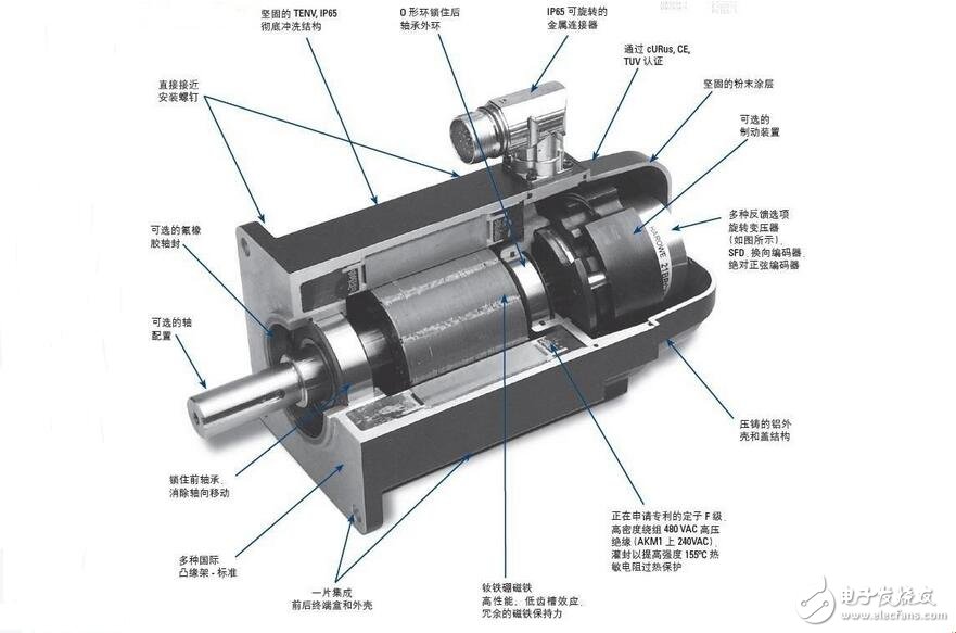
1. A servo system (servomechanism) is an automatic control system that enables an output controlled amount of an object to follow an arbitrary change of an input target (or a given value). The servo is mainly positioned by pulse. Basically, it can be understood that when the servo motor receives one pulse, it will rotate the angle corresponding to one pulse to realize the displacement. Because the servo motor itself has the function of emitting pulses, the servo motor has every When an angle is rotated, a corresponding number of pulses are emitted, so that the pulse received by the servo motor forms an echo, or a closed loop, so that the system knows how many pulses are sent to the servo motor, and how many pulses are received at the same time. In this way, the rotation of the motor can be controlled very accurately, so that accurate positioning can be achieved, which can reach 0.001 mm. DC servo motors are divided into brushed and brushless motors. The brush motor has low cost, simple structure, large starting torque, wide speed regulation range, easy control, maintenance, but inconvenient maintenance (replacement of carbon brushes), electromagnetic interference, and environmental requirements. It can therefore be used in cost-sensitive general industrial and residential applications.
The brushless motor is small in size, light in weight, large in output, fast in response, high in speed, small in inertia, smooth in rotation and stable in torque. The control is complex, and it is easy to realize intelligence. The electronic commutation mode is flexible, and can be square wave commutation or sine wave commutation. The motor is maintenance-free, has high efficiency, low operating temperature, low electromagnetic radiation and long life, and can be used in various environments.
2. AC servo motor is also a brushless motor, which is divided into synchronous and asynchronous motors. At present, synchronous motors are generally used in motion control. It has a large power range and can achieve a large power. High inertia, the highest rotational speed is low, and it decreases rapidly as power increases. Therefore, it is suitable for applications with low speed and smooth operation.
3. The rotor inside the servo motor is a permanent magnet. The U/V/W three-phase electric motor controlled by the driver forms an electromagnetic field. The rotor rotates under the action of the magnetic field. At the same time, the encoder feedback signal from the motor is supplied to the driver. The driver is based on the feedback value. Compare the target value and adjust the angle of the rotor rotation. The accuracy of the servo motor is determined by the accuracy (number of lines) of the encoder.
The difference between the AC servo motor and the brushless DC servo motor: AC servo is better because it is sine wave control and the torque ripple is small. The DC servo is a trapezoidal wave. But DC servo is simpler and cheaper.
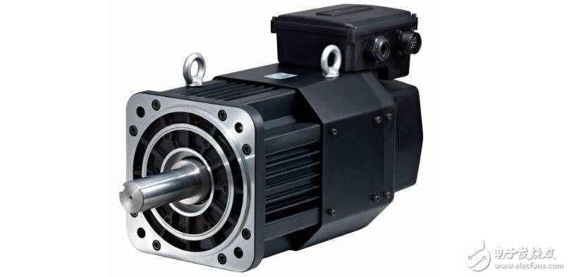
The servo can be used as an AC or DC motor. Early general servo DC motors, because only the type of control of large currents was passed through the sequence for many years. As transistors become capable of controlling large currents and switching large currents at higher frequencies, AC servo motors become more frequently used. Early servos were designed for servo amplifiers. Today, one type of motor design application is raised, possibly using a servo amplifier or a variable frequency controller, which means that the motor can be used in a servo system in one application and using a variable frequency drive in another application. Some companies also require any closed loop system that does not use a stepper motor servo system, so it is possible that a simple AC induction motor is connected to a speed controller called a servo motor.
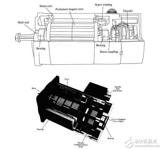
Some changes must be made to any movement, the purpose is to act as a servo in the cludes, operate a series of speeds without overheating, operate at zero speed and maintain sufficient torque to hold the load position, operate at very low speed Not overheating for a long time. Older engine cooling fans are already connected directly to the motor shaft. When the motor runs slowly, the fan will not move enough air to cool the engine. Newer engines have a separate fan installation to provide optimum cooling air. This fan is powered by a constant voltage source so that it will in turn be at the maximum speed at any time regardless of the speed of the servo. One of the most practical types of motor servo systems is the permanent magnet (afternoon) type engine. The permanent magnet type motor with a voltage of external winding can be AC ​​voltage or DC voltage. Permanent magnet type motors are similar to other types of motors that were proposed before the afternoon. Figure 11-83 shows a permanent magnet motor and a diagram of a cross-sectional view. 11-84 shows a permanent magnet motor with a sectional view. From the pictures and charts you can see the housing, the rotor and the stator are all looking very similar to the front-type permanent magnet motor. The main difference is this type of engine, which may reduce the ability of the gear to move a larger load quickly from a stand still position. This type of permanent magnet motor also has a housing with an encoder or resolver built-in motor. This ensures that the device will accurately indicate the position or speed of the motor shaft.
The purpose of the brushless servo brushless servo motor is to carry out activities, brushes. This means that the brush supply for commutation must now be provided electronically. Electronic commutation is done by switching the transistor and turning it off at the appropriate time. Figure 11-85 shows three examples of voltage and current waveforms sent to a brushless servo motor. Figure 11-86 shows an example of these three winding brushless servo motors. The main point of the brushless servomo factor is that it can use any AC voltage or DC voltage.
Figure 11-85 shows three types of voltage waveforms that can be used in power brushless servo motors. Figure 11 - 85a shows the trapezoidal electromotive force (voltage) input and the square wave current input. Figure 11 - 85b shows the sinusoidal input voltage and square wave current waveform of the waveform. Figure 11 - 85C shows the sinusoidal input waveform and the sinusoidal current waveform. Sinusoidal input and sinusoidal current waveforms are the most popular voltage supplies for brushless servo motors.
Figure 11-86 shows a variable frequency driver for a transistor output stage similar to three sets of transistors. In the picture. The three winding motors connected to the 11-86a transistor are in the same way as the variable frequency drive. In the picture. The output transistor of a one-liter-86b waveform appears as three different sine waves. Based on the control circuit of the waveform, the map is displayed in each transis. 11-86c. Figure 11-86d shows the drive waveform for the back EMF.
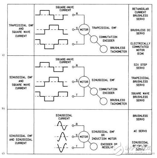
Figure 11-85 (a) The form of the trap ezoidal input voltage and square wave current wave. (b) Sinusoidal input voltage and sinusoidal voltage and square wave output voltage wave form. (c) Sinusoidal input voltage and sinusoi current waveform. This has become the most popular type of brushless servo control.
Servo controller
The servo controller has become a servo motor that is not just an amplifier. Today, the servo controller must be able to make a series of decisions and provide a means to receive signals from external sensors and control systems, and to signal the interface between the host controller and the PLC, possibly with the servo system. Figure 11-87 shows several servo motors and amplifiers for the picture. The various components in this picture look similar to various other types of motors and controllers.
Figure 11-88 shows the diagram of the servo controller so that you can see some differences with other types of motor controllers. The controller in this picture is a DC servo motor. The controller has three ports that make signals or send signals to the controller. The power supply, servo motor, and tachometer are connected to the controller at the bottom of port P3. As you can see, the supply voltage is 115 volts single phase AC. A major disconnected series with Li line. Isolated step-down transformer powered by Li and N lines. The secondary voltage across the front can be 20 and 85 volts of any voltage. The controller is grounded at 8. You should remember that the ground at this point is used to provide a system for short-circuit protection of all metal parts.
The servo motor is connected to the terminal controller at 4th and 5th. Terminal 5 + and terminal 4 -. Terminal 3 provides shielded wiring, motors and controls for the ground. Connect the tachometer to terminals 1 and 2. Terminal 2 is + and terminal 1 -. In this shield cable grounding motor case. Wires connected to this port will be larger than wires connected to other ports because they must be able to carry larger motor currents. If the motor uses an external cooling fan, this will be connected through this port. In most cases, the cooling fan will be maintained at a constant level with a single or three phase AC voltage, such as 110 volts or 240 volts.
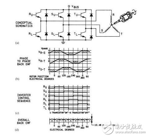
Figure 11-86 (a) The sistors are connected to three winding brushless servo motors. (b) Three independent voltages of the waveform for the three wind messages of the power motor. (c) The waveform signal is used to control the transistor sequence, providing the overall back EMF of the waveform before (d) the waveform.
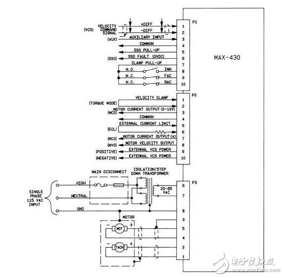
Figure 11.88 shows the servo controller. The digital (switch) signal and analog signal shown in this figure are sent to the controller and the signal controller is sent back to the host controller or PLC.
The signal of the command is sent to the controller through the port. The terminal's command signal is 1 and 2. Terminal 1 is + and terminal 2 -. This signal is a kind of signal, which means it is not a grounding or disagreement reason that may be the same as any other part of the circuit. Some additional auxiliary signals are also connected through port 1 . These signals include suppression (isoniazid), which is used to disable driving from an external controller, and forward and reverse commands (Congo and absorbing coating), which emits a voltage motor to the controller, making it Directional rotation or twisting. In some applications, the largest travel limit switch and reverse maximum travel limit switch connection, if the travel machine moves to the extreme position so that it touches the overtravel limit switch, it will automatically stimulate the drive and start traveling. The opposite direction is developing.
The port also provides several digital output signals that can be used to send fault signals or other information, such as "driver operation" back to the main controller or PLC. The port is basically a fully digital (switched) signal of the interface.
Port P2 is the analog (0 - maximum) signal of the interface. Typical signals, this car includes motor current and motor speed signals that are sent to the servo controller to the host or company where they can be used to verify the logic to ensure that the controller sends the correct information to the motor. Input signals from the host or PLC can also be sent to the controller to set the maximum current and speed of the drive. In the new digital drive, these values ​​control the drive parameters that are programmed into the drive.
Geared Stepper Motor,Planet Gearbox,Spur Gearbox,Nema23 Geared Electric Motor
Changzhou Sherry International Trading Co., Ltd. , https://www.sherry-motor.com