Questions and Answers:
How to use the *linux driver?
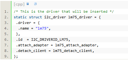
Looking at the lm75.c code, I found this temperature sensor using the I2C bus. The code to see the i2c driver interface definition is as follows, and the previous character driver interface is not the same.

Searched in the linux device driver book, not introduced in this book.
That's not bad. Especially the latter is right. I2C has many applications in reading the sensor on the motherboard, but it was added in a relatively new version of the Linux kernel version. No wonder LDD is not mentioned in this book.
Look again at the callback function in the data structure above, what exactly is more clear. According to the function content, the driver will automatically detect the device on the I2C bus at the time of loading, so the temperature sensor will be found automatically. Lm75_update_device() is a function used to poll the temperature sensor for readings.
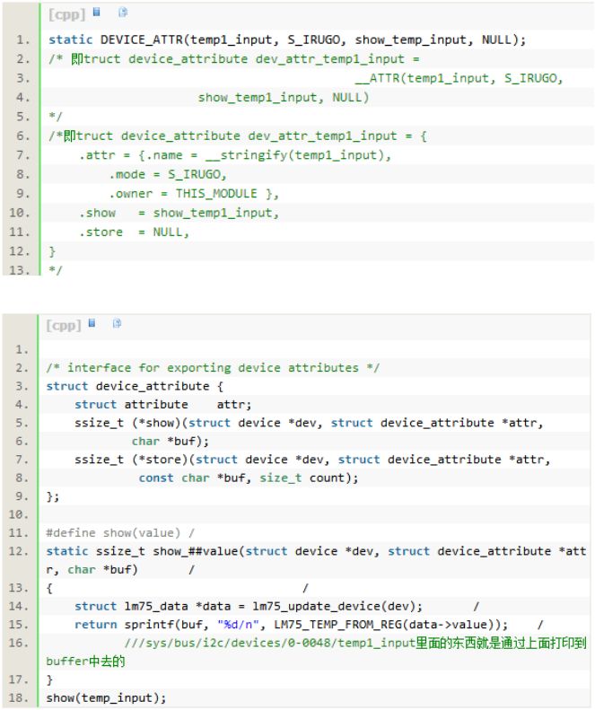
According to the article guidelines, look at the device's /sys/bus/i2c/. Now that you have the lm75 sensor data, reading directly has data, and the data will change, as follows:
Root:~# cat /sys/bus/i2c/devices/0-0048/temp1_input-31500
* The reading is negative. What kind of reading is normal? Added debugging information to the driver code, printed out the value of the register read on the sensor, not the same as read out on the file system.
Look at linux-2.6.20.21/Documentation/hwmon/lm75 and understand that lm75 is an industry standard. Therefore, the lm75 driver in Linux supports multiple temperature sensors.
Looked at the chip on the board, is lm75A. Downloaded a datasheet on the Internet, above shows a total of 9-bit to control the reading. The head position is positive and negative, followed by the 8-bit value.
Adding debug information to the driver code only prints the last 8-bit of the register value, and the test results in the temperature tester appear to be reasonable.


Then fix the kernel's lm75.h code (read the last 8 bits and judge the positive and negative values ​​according to the size) and pass the test.
A membrane switch consists of various layers laminated together. The layers of a basic membrane switch construction include: a membrane overlay, spacer, printer circuit, rear adhesive, and tail filler. Depending on the environment and requirements of the application into which the membrane switch plugs into, the construction can vary.
Membrane Switch Assemblies,Lcd Display Membrane Switch,Tactile Membrane Switch Keypad,Overlay Tactile Membrane Switch
KEDA MEMBRANE TECHNOLOGY CO., LTD , https://www.kedamembrane.com