XOR gates are logic gates that implement logical XOR in digital logic. There are multiple inputs and one output, and the multi-input XOR gate can be composed of 2-input XOR gates. If the levels of the two inputs are different, the output is high 1; if the levels of the two inputs are the same, the output is low 0. That is, if the two inputs are different, the XOR gate outputs a high level. Although XOR is not one of the basic operations of the switch algebra, a discrete XOR gate is quite commonly used in practical applications. Most switching technologies do not directly implement the XOR function, but instead use multiple gate designs.
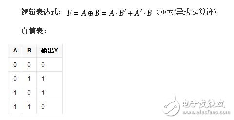
symbol

The XOR gate is composed of an OR gate, a NAND gate and an AND gate, so it cannot be expressed by a simple circuit diagram.
Circuit implementation of XOR gateNetizen: Bigan W Question: The XOR gate is when the two switches are closed or opened at the same time, the small bulb will be extinguished, one switch will be closed, and the other will be illuminated when the small bulb will be illuminated. It is better to have a circuit drawing.
The solution is roughly divided into two types:
One is to use a special switch (single-pole double-throw switch) to simulate the effect of the XOR gate, but that can be said to be just a logic gate on the "perceptual cognition".
The second is to build three basic logic gates using special components, and finally merge them into one XOR gate.
Using six electromagnetic relays, two two basic logic gates are combined and merged into an XOR gate.
The circuit diagram is as follows, this circuit is a DC circuit:
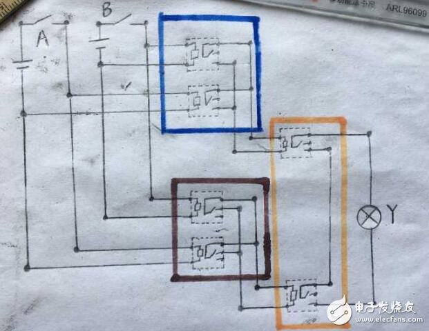
In the figure, AB is the condition (input) and Y is the result (output).
Dots indicate that the wires are connected.
There are six electromagnetic relays in the dotted line.
The circuit inside the blue frame constitutes an OR gate.
The circuit inside the brown frame constitutes a NAND gate.
The circuit inside the yellow frame forms an AND gate.
To understand this circuit diagram, the key is to understand the role of the electromagnetic relay.
In the figure, the left half of the dotted line representing the relay represents the coil, and the right half is simplified to the structure of a single-pole double-throw switch (I really don't know if this is a general drawing method QAQ). All components can be found in the junior high school laboratory.
In addition, the XOR implementation circuit is still quite complicated, I hope these two pictures can help everyone.
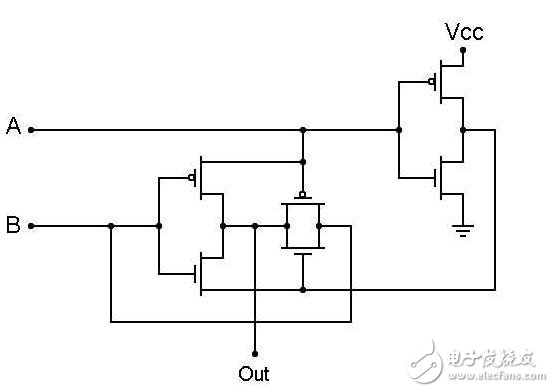
CMOS XOR gate circuit representation
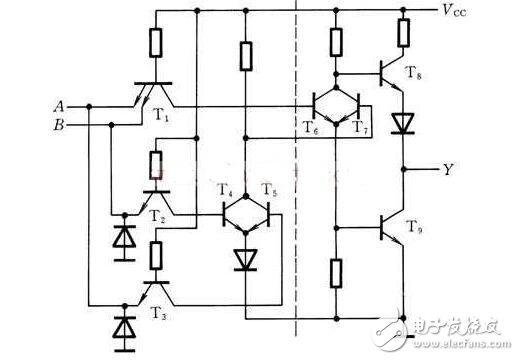
Triode XOR gate representation
The sensor includes linear encoder and rotary encoder, which is used for the position measurement of speed, displacement and angle. Yuheng optics can provide rotary encoders based on optical, magnetic and gear principles, linear encoders based on optical principles and supporting products.
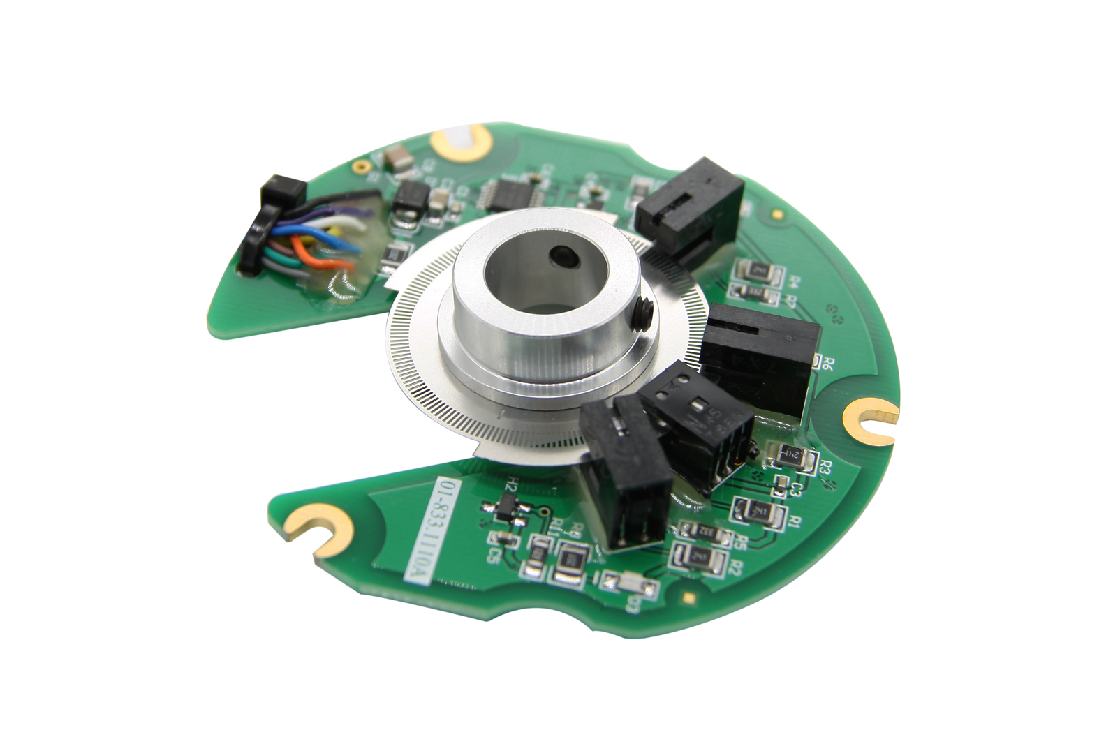
Custom Sensor,Clintegrity Encoder,Absolute Angle Encoder,Small Rotary Encoders
Yuheng Optics Co., Ltd.(Changchun) , https://www.yhenoptics.com