The servo motor can control the speed and position accuracy very accurately, and can convert the voltage signal into torque and speed to drive the control object. The servo motor rotor speed is controlled by the input signal and can react quickly. It is used as an actuator in the automatic control system, and has the characteristics of small electromechanical time constant, high linearity, and starting voltage, which can receive the received electrical signal. Converted to an angular displacement or angular velocity output on the motor shaft. Divided into two major categories of DC and AC servo motor, its main feature is that when the signal voltage is zero, there is no rotation phenomenon, and the rotation speed decreases uniformly with the increase of torque.
DC servo motor, which comprises a stator, a rotor core, a motor shaft, a servo motor winding commutator, a servo motor winding, a speed measuring motor winding, a speed measuring motor commutator, and the rotor core is stacked and fixed by a steel sheet It is formed on the motor shaft.
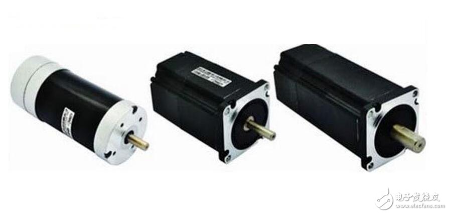
DC servo motor refers to DC brushed servo motor - high motor cost, complex structure, large starting torque, wide speed range, easy control, maintenance, but inconvenient maintenance (replacement of carbon brushes), electromagnetic interference will occur. The environment is required. Therefore it cannot be used in general industrial and civilian applications that are cost sensitive.
The DC servo motor also includes a DC brushless servo motor—the motor is small in size, light in weight, large in output, fast in response, high in speed, small in inertia, smooth in rotation, stable in torque, and limited in motor power. It is easy to realize intelligence, and its electronic commutation mode is flexible, and it can be commutated by square wave or sine wave. Motor maintenance-free, there is no carbon brush loss, high efficiency, low operating temperature, low noise, small electromagnetic radiation, long life, and can be used in various environments.
The concept of speed regulation has two aspects:
(1) Change the motor speed: When the command speed changes, the speed of the motor changes accordingly, and it is hoped to reach the new command speed value with the fastest acceleration and deceleration;
(2) When the command speed does not change, the speed of the motor remains stable.
In order to adjust the motor speed and direction, it is necessary to control the magnitude and direction of the DC voltage. How to control it?
The role of the DC servo motor speed control unit: converts the speed command signal into the voltage value of the armature to achieve the purpose of speed adjustment.
The speed control method commonly used by the DC motor speed control unit: thyristor (thyristor) speed control system; transistor pulse width modulation (PWM) speed control system.
1, thyristor speed control system
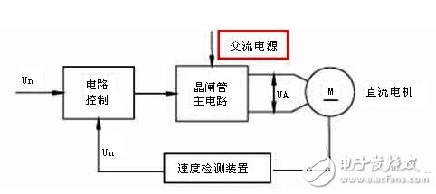
When the AC power supply voltage is constant, when the control voltage Un* is changed, the armature voltage Ud of the DC motor is changed by the control circuit and the thyristor main circuit to obtain the motor rotation speed required by the control voltage Un*. The actual voltage Un of the motor is compared with Un* as feedback to form a speed loop for the purpose of improving the mechanical characteristics of the motor during operation.
The main circuit of the thyristor speed control system uses a high-power thyristor. The role of high power thyristors:
(1) Rectification. Turning the AC power of the grid into DC; amplifying the control power of the regulation loop to obtain a higher voltage and a larger current to drive the motor.
(2) Inverter. In the reversible control circuit, when the motor brakes, the inertia energy of the motor operation is converted into electric energy, and is fed back to the AC grid to realize the inverter.
In order to control the thyristors, a trigger pulse generator must be provided to generate the appropriate trigger pulses. The pulse must be synchronized with the frequency and phase of the power supply to ensure proper triggering of the thyristor
The main circuit consists of a three-phase full-control bridge type anti-parallel reversible circuit composed of high-power thyristors. It is divided into two parts (I and II). Each part is connected by three-phase bridge type, and the two sets are reversed and connected to realize forward rotation. And reverse.
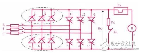
Each of the thyristors is simultaneously turned on to form a loop. In order to ensure that the two thyristors connected in series can be turned on at the same time after the switch-on or the current is turned off, a trigger pulse must be simultaneously issued for one thyristor of the common anode group and one thyristor of the common cathode group.
2, PWM speed control system
Principle: Using the switching action of high-power transistors, the DC voltage is converted into a square wave voltage of a certain frequency and applied to the armature of the DC motor; the average voltage of the armature is changed by adjusting the square wave pulse width to adjust the motor. Rotating speed.
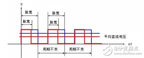
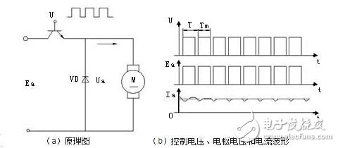
Average value of DC motor voltage

Where T is the pulse period and Ton is the on time
Features: The control circuit is simple, no additional shutdown circuit is required, and the switching characteristics are good. Widely used medium and small power DC servo system.
(1) The composition of the PWM system
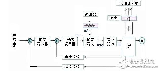
USr - the DC voltage converted from the speed command;
U△——triangular wave;
USC - the output of the pulse width modulator (USr + U â–³);
Ub—The pulsed output of the modulator output, the pulse voltage converted by the base drive.
Control loop: speed regulator, current regulator, fixed frequency oscillator and triangle wave generator, pulse width modulator and base drive circuit.
Difference: Compared with the thyristor speed control system, the speed regulator and the current regulator have the same principle. The difference is the pulse width modulator and power amplifier.
(2) PWM system pulse width modulator
Function: Convert the voltage amount into a rectangular pulse that can be adjusted by the control signal, and provide a pulse width voltage whose width can be adjusted by the speed command signal for the base of the power transistor.
Composition: Modulation signal generator (triangular wave and sawtooth wave) and comparison amplifier.
3, all digital DC speed control system
In the all-digital DC speed regulation system, only the input signal and the output signal of the power conversion component and the execution component are analog signals, and the remaining signals are digital signals, which are implemented by a computer through an algorithm.
The calculation speed of the computer is very high. The input and output values ​​of the current loop and the speed loop can be calculated within a few milliseconds, and the data of the control square wave is generated, thereby controlling the rotational speed and torque of the motor. The all-digital speed regulation is characterized by discretization, that is, the control data is given once per sampling period.
In one sampling period, the computer completes the calculation and output of the control data of the current loop and the speed loop, and controls the speed and torque of the motor once.
Principle of speed regulation of DC servo motorComposition: It consists of three parts: magnetic pole (stator), armature (rotor), brush and commutator. The slenderness of the structure is mainly to reduce the moment of inertia, so as to meet the requirements of the fast response of the servo motor.
Working principle: The DC power supply is connected between the two brushes, the current is passed into the armature coil, and the magnetic lines are cut to generate electromagnetic torque.
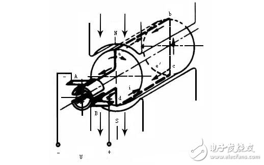
The direction of the current is: the current in the active side of the N pole is always one direction, and the current in the active side of the S pole is always the other direction. This causes the directions of the electromagnetic forces received on the two sides to coincide, and the armature thus rotates. Therefore, when the effective side of the coil is turned from the N pole to the S pole, the direction of the current must be changed simultaneously so that the direction of the electromagnetic force does not change. This must be achieved by a commutator.
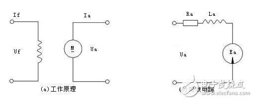
Electromagnetic torque

Inductive potential and speed

Armature loop voltage balance equation


Formula of the speed of the excited DC servo motor

The relationship between DC motor speed and torque n = f (T) is called mechanical characteristics (static characteristics). The difference Δn between the motor speed and the ideal speed reflects the mechanical hardness of the motor. The smaller Δn (the smaller the influence of torque on the speed change), the harder the mechanical characteristics.
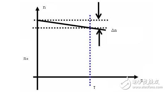
There are three basic speed control modes for DC motors: adjusting the resistance Ra, adjusting the armature voltage Ua, and adjusting the value of the magnetic flux Φ. Armature resistance speed regulation is rarely used, its disadvantages: uneconomical, to get low speed, R is very large, it consumes a lot of electric energy; low speed, very soft characteristics, poor running stability; poor adjustment smoothness, laborious operation.
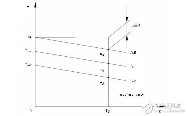
When adjusting the armature voltage (regulation speed regulation), the mechanical characteristics of the DC motor are a set of parallel lines, only changing the ideal speed n0 of the motor, maintaining the original hard mechanical characteristics, so the voltage regulation is mainly used for servo advancement. Speed ​​control for the drive system motor. If the value of Δn is large, it is impossible to achieve a wide range of speed regulation. Permanent magnet DC servo motors have a small Δn value. Therefore, permanent magnet DC motors are often used in feed systems.
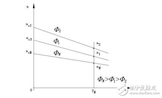
Adjusting the magnetic flux (magnetic speed regulation) not only changes the ideal speed of the motor, but also makes the mechanical characteristics of the DC motor soft, so the speed adjustment is mainly used for motor speed adjustment of the machine spindle.
We are dedicated charging solution Manufacturer since 2005.
Supply various Power Station including Portable Power Stations, Solar Power Generators, Smallest Generator etc.
Manufacturing high quality products for customers according to international standards, such as CE ROHS FCC REACH UL SGS BQB etc.
To constantly offer clients more innovative products and better services is our consistent pursuit.
TOPNOTCH INTERNATIONAL GROUP LIMITED , https://www.mic11.com