With the improvement of people's living standards and the accelerated pace of life, the incidence of cardiovascular diseases has risen rapidly and has become one of the main factors threatening human health. Electrocardiogram is the main basis for the treatment of such diseases. It has the advantages of reliable diagnosis, simple method and no harm to patients. It has become more and more important in modern medicine. The conventional electrocardiogram is the electrocardiogram recorded by the electrocardiograph in the case of a patient lying down. It lasts only a few s~1 m, and only a small amount of information about the state of the heart can be obtained. Therefore, even if arrhythmia occurs within a limited time, it is discovered. The probability is also very low. Therefore, it is necessary to perform long-term real-time monitoring of the patient through the corresponding monitoring device, and record the patient's ECG data. Because of the sudden nature of heart disease, patients can not stay in the hospital for a long time, but they need to be monitored by medical staff in real time, so it is more important to develop corresponding portable ECG monitoring products. This paper proposes an ECG diagnostic system based on a remote diagnostic platform, which enables portable, easy-to-use, real-time monitoring and reduced diagnostic costs.
1 mode implementationThe remote diagnosis mode is mainly based on two reasons: First, portability, traditional ECG detection equipment is difficult to carry around due to its limitations, patients can only go to a specific location when testing, not only can not achieve real-time, but also increased Medical cost; Second, ease of use, traditional equipment has certain professional requirements for operators, often patients are difficult to operate. The remote diagnosis mode is proposed, and the system is divided into a user terminal and a remote service terminal. The user only needs to carry the user terminal device, and only needs to operate the user terminal to isolate the professional operation to the remote service terminal, thereby realizing the portability. With ease of use.
In the remote diagnosis mode, the user terminal mainly realizes real-time collection of ECG signals, stores and forwards data, and controls the GPRS Communication Module to be sent to the remote service terminal; the remote service terminal mainly undertakes analysis and processing of data, and can even analyze with experts online. And real-time diagnosis, and finally return the diagnosis result to the user terminal.
2 system designThe portable ECG diagnosis system is mainly composed of front-end acquisition circuit, user-side main control module, two GPRS terminals and remote server. The basic structural block diagram is shown in Figure 1.

The front-end acquisition circuit in Figure 1 mainly undertakes the function of ECG signal acquisition. The collected signal is sent to the user-side main control module after preliminary filtering and amplification, and the main control MCU performs A/D conversion and some basic processing on the ECG signal data. It is then stored in the EEPROM and awaits the user's command indication. The GPRS terminal is responsible for the transmission and reception of data. After receiving the data sent by the user, the remote server performs detailed processing, and obtains the diagnosis result and sends the result back to the user terminal.
2.1 front-end acquisition circuitThe front-end acquisition circuit is mainly composed of an electrocardiogram electrode, a front differential low-pass filter circuit, a front differential amplifier circuit, a high-pass filter circuit, a main amplification circuit, a right leg drive circuit, an overvoltage protection circuit, and a power module. as shown in picture 2.
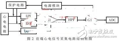
An electrocardiogram waveform can be traced by placing two electrodes on two different points on the surface of the human body and connecting them to the electrocardiograph through the wires. The placement of the electrodes in the electrocardiogram and the connection of the wires to the amplifier are called ECG leads. The standard bipolar lead I is used in the design. It is the surface electrocardiogram obtained by the potential difference between the two limbs. The position of the electrode and the connection with the amplifier are: the left upper limb (L) is connected to the positive input of the amplifier, and the right upper limb (R) is connected to the negative input of the amplifier. At the same time, the right lower limb (RF) should be directly floated. In this system, the right lower limb is connected to the output of the right foot electrode driver and is indirectly grounded.
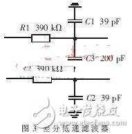
In this circuit, a differential low-pass filter circuit is designed to prevent RFI rectification errors, as shown in Figure 3. In addition to providing immunity to RFI, this filter provides additional input overload protection because resistors R1, R2 help isolate the input circuitry of the instrumentation amplifier from external sources. C3 bridges the bridge output so that C3 is effectively connected in parallel with the series combination of C1 and C2. C3 is very effective in reducing any AC-CMR (AC-Common Mode Rejection) errors due to mismatch.
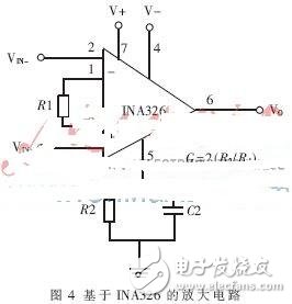
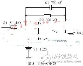
The most important part of the ECG signal acquisition circuit is the amplification circuit. Because the ECG signal is very weak, and there are many kinds of interference signals such as polarization voltage, thermal noise and noise generated by the instrument during the acquisition process, it has a great influence on the detection and analysis of subsequent characteristic waveforms. Most of these interferences are common mode interference, so the preamplifier is required to have a sufficiently high common mode rejection ratio, and at the same time, to suppress the "baseline drift" of the signal, there must be a small enough temperature drift. The design uses TI's INA326 amplifier, the circuit shown in Figure 4.
The integrated power transducer can measure power parameters in three-phase power grid
with high accuracy, and has extended functions such as communication interface and analog output.
Integrated Power Transducer,3P4W Reactive Power Transducer,3P4W Sfere Reactive Power Transducer,3P4W Power Transducer
Jiangsu Sfere Electric Co., Ltd , https://www.elecnova-global.com