A steering gear is an executing component that controls the rotation of the aircraft's rudder (control surface) in an autopilot. There are: 1 electric steering gear, composed of electric motor, transmission components and clutch. The autopilot's command signal is accepted to operate. When the aircraft is manually piloted, the clutch components remain disengaged and the transmission components do not function. 2 Hydraulic steering gear, consisting of a hydraulic actuator and a bypass valve. When manually piloting the aircraft, the bypass valve is opened, and the manual communication is not hindered due to the hydraulic communication between the two sides of the actuator piston. In addition, there are electrohydraulic servos, referred to as "electrohydraulic servos."
The size of the servo is determined by the external equipment according to the rules of the classification society. The size of the torque is mainly considered when selecting the model. It is also an indispensable science for how to carefully select the steering gear that meets the needs of the economy. This paper first introduces the working principle of the servo, secondly describes the servo control principle and the following characteristics of the servo, and finally introduces the servo control method and the servo speed control.
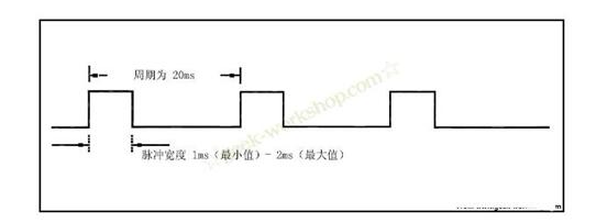
How does the servo work?Servo servos are controlled by variable-width pulses that are used to transmit pulses. The pulse parameters have minimum, maximum, and frequency. In general, the servo's reference signal has a period of 20ms and a width of 1.5ms. The position of this reference signal is defined as the middle position. The servo has a maximum rotation angle. The definition of the middle position is exactly the same from this position to the maximum angle and the minimum angle. The most important point is that the maximum rotation angle of different servos may not be the same, but the pulse width in the middle position is certain, that is 1.5ms. As shown below:
The angle is generated by the continuous pulses from the control line. This control method is called pulse modulation. The length of the pulse determines how much the servo rotates. For example, a 1.5-millisecond pulse goes to the middle position (for a 180-degree servo, it is a 90-degree position). When the control system issues an instruction to move the servo to a certain position and allow him to maintain this angle, the influence of the external force will not cause his angle to change, but this is the upper limit, and the upper limit is his maximum torque. Unless the control system continuously sends pulses to stabilize the steering angle, the steering angle will not be constant.
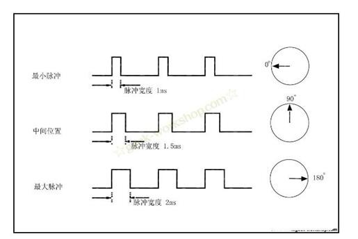
When the servo receives a pulse less than 1.5ms, the output shaft will take the middle position as the standard and rotate it counterclockwise by a certain angle. The opposite is true when the received pulse is greater than 1.5ms. Different brands, even different servos of the same brand, will have different maximum and minimum values. In general, the minimum pulse is 1ms and the maximum pulse is 2ms. As shown below:
The control signal enters the signal modulation chip from the receiver's channel to obtain the DC bias voltage. It has a reference circuit internally, generates a reference signal with a period of 20ms and a width of 1.5ms, and compares the obtained DC bias voltage with the voltage of the potentiometer to obtain a voltage difference output. Finally, the positive and negative voltage difference is output to the motor driver chip to determine the positive and negative motor rotation. When the motor rotates at a certain speed, the potentiometer is rotated through the cascade reduction gear so that the voltage difference is 0 and the motor stops rotating.
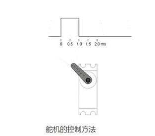
The servo control generally needs a time base pulse of about 20ms. The high level part of the pulse is generally an angle control pulse part within the range of 0.5ms-2.5ms, and the total interval is 2ms. Take 180 degree angle servo as an example, then the corresponding control relationship is this:
0.5ms--------------0 degrees;
1.0ms------------45 degrees;
1.5ms------------90 degrees;
2.0ms-----------135 degrees;
2.5ms-----------180 degrees;
Follower Characteristics
Assume now that the servo is stable at point A. At this time, the CPU sends out a PWM signal and the servo rotates from point A to point B at full speed. In this process, it takes a while for the servo to move to point B.
Hold time Tw
When Tw ≥ △T, the servo can reach the target and there is time remaining;
When Tw ≤ △T, the servo cannot reach the target;
Theoretically: When Tw = â–³T, the system is the most consistent, and the servo moves fastest.
In the actual process, w is not the same, and the limit ΔT during continuous motion is difficult to calculate.
When the PWM signal changes in order of minimum change (1DIV = 8us), the servo has the highest resolution, but the speed will slow down.
The servo is generally controlled by a single-chip microcomputer or a digital circuit. Servo work is mainly related to the high-level duration of the control line, generally divided by 0.5ms (milliseconds). If the duration is 0.5ms, 1ms, 1.5ms, 2ms, 2.5ms, the rudder turns different angles. .
The servo control generally needs a time base pulse of about 20ms. The high-level part of the pulse is generally an angle control pulse part within the range of 0.5ms to 2.5ms. Taking a 180-degree angle servo as an example, the corresponding control relationship is: the pulse is set to 0.5 ms, the rotation angle is 0 degrees, the pulse is set to 1.0 ms, the rotation angle is 45 degrees, the pulse is set to 1.5 ms, and the rotation angle is 90 degrees; The 2.0 ms rotation angle is set to 135 degrees; the pulse setting is 2.5 ms rotation angle is 180 degrees.
For 180 degree servos:
The speed of rotation of the steering gear depends on the difference between the starting angle and the target angle. The greater the difference, the faster the rotation and the slower the angle when approaching. So there is no special function to control the speed. But when you are turning at a large angle, you can use a program to set it to a few small angles, so that you can slow down. It also slows through delay, but only increases the voltage when it is fast.
For 360 degree servos:
The parameters of write() or writeMicroseconds() determine the speed of the servo, but they can also be decelerated by delay() or delayMicroseconds().
Laser radar contains LSPD safety laser scanner and LS laser radar. LSPD safety laser scanner is type 3 with CE certificate. It can be used for agv safety and industrial area protection. LS laser radar is for agv guide. Many famous agv manufacturers has installed LS laser radar to guide their agvs. Our cooperating brand contains Quicktron, Mushiny, Aresbots, etc. Feedback from customers are quite posotive.
Laser Radar,Auto Guided Vehicle Guide Radar,Sick Laser Radar,Safety Scanner,Safety Laser Scanner,Ls Series Laser Radar
Jining KeLi Photoelectronic Industrial Co.,Ltd , https://www.sdkelien.com