Introduction to the principle and application of non-contact charging technology for passenger cars
The characteristic of electric vehicles is that they can be connected to a power cord for charging at home and parking lots. However, due to the problem of continuous driving distance, the number of times of charging is more frequent than that of gasoline vehicles, so the convenience may be reduced. What is expected to solve this problem is the “non-contact charging†method that uses electromagnetic induction and does not require wire charging.
The method of charging without wires is called "non-contact charging". In electric vehicles and hybrid buses, some models have started to use non-contact charging. Recently, the possibility of adopting EVs (electric vehicles) for passenger vehicles is increasing.
The "non-contact charging" buses were tested at Haneda Airport in February 2008 and Nara in October 2009. The charging method uses a method based on electromagnetic induction. First of all, the reason for using non-contact charging in the bus is that the driver has high driving skills and can accurately stop the car to the position where there is a power transmission coil. And, the operation route is determined, and only a little installation cost of charging facilities is required.
As for the passenger car EV, it is necessary to develop a technology that can charge the parking vehicle with some deviations, and a large-scale charging infrastructure needs to be installed. Therefore, the industry generally believes that it will take some time to adopt non-contact charging in passenger cars.
Nissan is most active in the practical use of non-contact charging systems. The company is considering adopting it in the second-generation EV launched from 2013 to 2015. One of the second generation EVs was the concept car "LandGlider" (Figure 1), which was unveiled at the Tokyo Motor Show in the autumn of 2009. It is assumed that electric power is transmitted between the power receiving unit disposed under the vehicle floor and the power transmitting unit disposed on the ground to realize non-contact charging.

Figure 1: Nissan's "LandGlider" electric car concept car unveiled at the Tokyo Motor Show in the autumn of 2009. It is envisaged to support non-contact charging. Consider achieving practicality around 2013.
Nissan believes that to popularize non-contact charging in passenger cars, it is necessary to develop technology and reduce costs. The main reason for non-contact charging is "EV charging will increase on the street."
Some users used to drive petrol cars to refuel at a frequency of 1 or 2 times per month, but instead of EVs they had to recharge every time they drove. The user must connect the power cord every time the battery is charged, which reduces convenience. "Just looking at the current method of charging with a power cord, some users will definitely feel that EV is more troublesome than gasoline cars" (Nissan Motor Planning and Advanced Technology Development Headquarters sees Yi Ming), this sense of crisis has made Nissan start to be active Develop non-contact charging business.
It is believed that: "The current EV has not fully developed its electrical characteristics. If non-contact charging can be practical, it can clearly show the difference between EV and gasoline vehicles, which can increase the added value of EV."
It is precisely because Nissan is the most concerned about the popularity of EVs, so it has a positive attitude towards diversification of charging methods. The company will expand its EV production scale from 50,000 units in 2010 to 200,000 units in 2012, ahead of other companies. It is estimated that 10% of the global new car market will be occupied by EVs in 2020.
If EVs are popularized, it is estimated that in addition to users who think they can be charged with electric wires, users who think that connection is troublesome and who want to use non-contact charging and users who want to use battery replacement. It is expected that the non-contact charging Nissan is developing will be used in high-end models and accessories. "The non-contact charging concept is intended for users who want to use it no matter how high the cost is. The user will bear the cost of tens of thousands of yen to hundreds of thousands of yen" (person sees).
According to the charging time, the EV charging method can be divided into ordinary charging and fast charging. Nissan's second-generation EV envisages ordinary charging using wires, and fast charging uses a non-contact charging system. Since cheap late-night electricity is used in the home, ordinary charging using electric wires can be used.
And supplemental charging on the street takes a short time to complete, so fast charging can be used. However, if you plug in and unplug the cable in a short period of time, especially in rainy weather, you will feel that the charging operation is inconvenient. Therefore, fast charging will also be prepared for non-contact.
There are three non-contact charging methods
There are three types of non-contact power supply. â‘ The electromagnetic induction method that has been applied to consumer electronic products, etc. â‘¡The magnetic resonance method that can supply power to several meters away, â‘¢The low-cost microwave method (table).

Electromagnetic induction is the most practical method, but there is a problem that the power transmission distance is relatively short. If the lateral deviation between the power transmission unit and the power receiving unit is large, the transmission efficiency will decrease. In addition, when used for fast charging, there is also a problem that the power transmission equipment on the infrastructure side costs money.
In response to these two problems, a magnetic resonance method that can extend the transmission distance and a microwave method that is expected to reduce costs have been developed.
Nissan is considering using electromagnetic induction. The company disclosed a non-contact charging system using electromagnetic induction at an advanced technology briefing held in July 2009 (Figure 2). The system was developed in cooperation with the Showa Aircraft Industry. The charging capacity varies depending on the size of the power transmission coil and the power receiving coil, but the charging capacity for passenger cars is about 1k to 30kW.
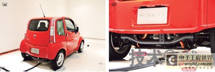
Figure 2: The experimental vehicle equipped with a non-contact charging system Nissan Motor announced the non-contact charging system in July 2009. (A) The prototype is the electric car "Hypermini" that was launched in 2000. It is planned to adopt a non-contact charging system in the next-generation EV launched in 2013. The non-contact charging system was developed in cooperation with the Showa Aircraft Industry. (B) Power transmission department and power reception department.
If the charging capacity of ordinary household charging is about 1.5kW (AC 100V × 15A), and the charging capacity of the fast charger on the street (DC 300-400V × 150A) is about 50kW, the charging capacity of the system developed by the Showa Aircraft is equivalent About half of the fast charger. In normal charging, it can be charged in the same time as the wire type. In fast charging, it can be charged in about 1.5 times the wire type.
Electromagnetic induction transmits power between the power transmitting coil and the power receiving coil. When an alternating current flows through the power transmission coil, a magnetic beam is generated between the power transmission and power reception coils, and as the magnetic flux changes, an AC current flows through the power reception coil (Figure 3). The system developed by Nissan in cooperation with Showa Aircraft has a transmission distance of about 10cm and a transmission efficiency of 90%. However, it is hoped that in the future, even if the car stops when the lateral deviation is 20-30cm, it will ensure the same transmission efficiency. Specifically, by reducing the loss of power transmission and power receiving coils, the transmission efficiency will be further improved than before.
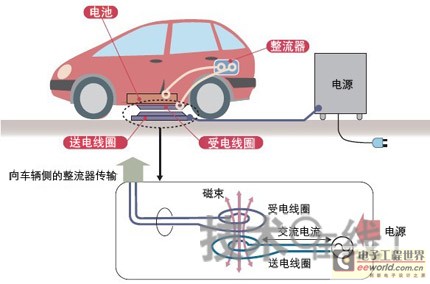
Figure 3: The principle of electromagnetic induction When an alternating current flows through the power transmitting coil, a magnetic beam is generated and passes through the power receiving coil. When the magnetic beam changes, the induced coil generates an induced electromotive force, and a current flows.
In addition, the two companies will also study the mechanism for detecting whether there is an animal intrusion and whether metal fragments enter between the power transmission and power reception departments during charging. Because if there are foreign objects during charging, eddy currents will be generated here, which may cause heat generation.
Magnetic resonance can transmit several meters away
The output power of the other two methods is still very small and is still in the research stage, but it is receiving much attention as the next-generation technology.
The non-contact transmission system using the magnetic resonance method has attracted the attention of global technicians since the MIT (Massachusetts Institute of Technology) was announced in 2007. In Japan, in August 2009, Nagano Japan Wireless announced the development of a power transmission system based on magnetic resonance (Figure 4). When the transmission distance between the power transmission and power receiving unit is 40cm, the transmission efficiency reaches 95% (Figure 5).
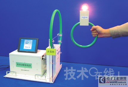
Figure 4: A trial production system developed by Nagano Japan Wireless, a power transmission system based on magnetic resonance. Compared with the electromagnetic induction method, it is suitable for long-distance transmission. The basic principle is electromagnetic induction. Using the control circuit to set the resonance frequency can reduce the resistance between the power transmission unit and the power receiving unit, and can transmit electricity to a distant place.
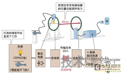
Figure 5: Magnetic resonance system (Nagano Japan Wireless) uses a high-frequency power supply to convert household power supply AC100V (50 to 60 Hz) to 13.56 MHz and transmit it to the power transmission department. It is converted into DC by the rectifier circuit of the power receiving unit and used for lighting or launching a model helicopter.
The basic principle of magnetic resonance is the same as electromagnetic induction. When a current flows through the power transmitting section, a magnetic beam is generated, and a current flows through the power receiving section. However, the difference is that instead of using a simple coil to constitute the power transmission section and the power reception section, an LC resonance circuit that uses both a coil (L) and a capacitor (C) is used. Another difference is that it has a control circuit that makes the two circuits have the same resonance frequency. The resonance frequency value changes according to the distance between the power transmission unit and the power reception unit. The two circuits are resonated by setting the appropriate resonance frequency using the control circuit.
The state of resonance of the two circuits is called "resonance", so it is named the magnetic resonance method. At resonance, the resistance between the power transmission unit and the power reception unit circuit can be minimized, and power can be transmitted within a distance of several meters.
The company estimates that the magnetic resonance method can ensure 90% efficiency within a transmission distance of 60cm (Figure 6). The electromagnetic induction method has a transmission efficiency of less than 90% within a distance of several centimeters, so the efficiency of the magnetic resonance method is higher.
The control circuit for setting the resonance frequency is connected to the power transmission unit. If the resonance frequency is not changed according to the transmission distance, the transmission efficiency will also decrease as quickly as electromagnetic induction (Figure 7). The transmission efficiency also changes with the diameters of the power transmitting and receiving parts, and the larger the area, the higher the transmission efficiency (Figure 8).
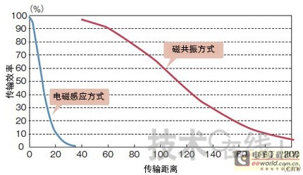
Figure 6: Power transmission method and transmission efficiency Electromagnetic induction transmission efficiency decreases within a few centimeters. The reduction in magnetic resonance transmission efficiency is gentle. When the diameter of the power transmission / reception unit is 40 cm.
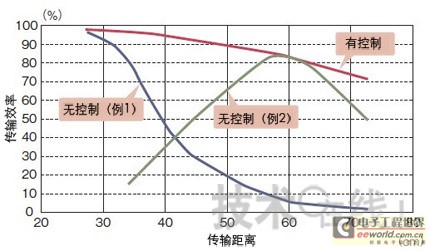
Figure 7: Resonance frequency control of the magnetic resonance method The resonance frequency is appropriately controlled according to the distance between the power transmission unit and the power reception unit, and the transmission distance will increase sharply. 
Figure 8: The relationship between the diameter of the power transmission and power receiving unit and the transmission distance The larger the diameter of the power transmission unit and the power receiving unit, the higher the transmission efficiency.
Although the current output power is only 30W, it is planned to increase to about 1kW in 2009. However, in actual use, it is necessary to comply with the radio wave method, verify the safety to the human body, and reduce the components, etc. in the same way as other methods.
In addition, the policy is "Introduce from areas with limited use, such as factory forklifts, and eventually apply to EVs" (Nagano Japan Wireless Research and Development Minister Akiya Taniya)
Low cost of microwave transmission
Mitsubishi Heavy Industries has developed a microwave-based charging system (Figure 9). The advantage is that it can be realized at low cost, and the disadvantage is that the transmission efficiency is only 38%.
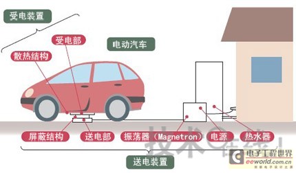
Figure 9: The microwave non-contact charging system being developed by Mitsubishi Heavy Industries is composed of a power transmitting device and a power receiving device. Between the shielded, radio waves will not leak.
The device that converts electricity into microwaves uses the 2.45GHz radio wave generator "Magnetron", which is the same device used in induction cookers (Figure 10). Since it can be mass-produced, each costs only about 10,000 yen, and the trial production system uses 12 such devices to generate microwaves to be transmitted. Its advantage is that "the total of power transmission and reception devices is only about 300,000 yen" (Mitsubishi Heavy Industries Co., Ltd., director of the space machinery technology department An Jianjian).
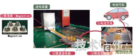
Figure 10: Mitsubishi Heavy Industries' trial production system uses Magnetron to oscillate microwaves, radiating from the opening of the power transmission section to the upper side through the metal waveguide.
At present, the efficiency of using Magnetron to generate microwaves is very low, so most of the electricity becomes heat, and the transmission efficiency is low.
Some people think that if the transmission efficiency is low, the charging time required to fully charge will be extended, resulting in an increase in electricity costs. However, Mitsubishi Heavy Industries believes: "From the current efficiency point of view, it is not suitable for fast charging, and it is possible to use it as a normal charging using late night power" (Anjian). If you use late-night electricity, the electricity cost is only about 10% to 20% of the fuel cost of gasoline vehicles, so even if the efficiency is worse, it is cheaper than gasoline. Therefore, it is advantageous to use non-contact charging for ordinary charging.
As for the power transmission device of the trial production system, Magnetron has a large amount of heat, so it is used as a cogeneration system that uses waste heat for hot water supply, increasing the overall energy efficiency to 70% (Figure 11).

Figure 11 The structure of the trial production system uses the Magnetron of the power transmission device to generate microwaves. The microwave is radiated from under the vehicle and received by the power receiving unit installed on the vehicle. Shield the power transmission unit and power reception unit to prevent microwave leakage.
The power receiving department will configure a "Rectenna" consisting of an antenna and a rectifier (diode). Microwaves are alternating current waves. After receiving them with an antenna, they are converted from alternating current to direct current by a rectifier circuit to charge the battery.
The Rectenna of the Ministry of Electricity is a few centimeters square, equipped with 48. A Rectenna generates a DC current with a voltage of 20V, and 48 are connected in series, which can boost to about 1kW equivalent to ordinary charging.
In order to prevent the leakage of microwaves from the power transmitting and receiving parts during charging, a shielding structure is adopted. When the system is running, the upper side of the power transmission section rises a few centimeters. A metal shield brush with a length of 6 cm is installed on the power transmission part. When the power transmission section is raised, the power transmission section and the power receiving section are covered by the shielding brush to prevent microwave leakage.
By setting the microwave leakage below the prescribed value of the radio wave method, the electronic equipment equipped in the vehicle and the heart rhythm regulator of the pedestrians nearby can be prevented from being affected. The shielding portion has a gap of 1 to 2 mm, but since the wavelength of the microwave is as long as about 12 cm, there is basically no leakage of radio waves between the gaps of 1 to 2 mm.
To ensure safety, the power transmission unit is equipped with a conduction sensor. It can be detected when the power transmitting unit and the power receiving unit are not in contact due to the deviation of the parking position. The power receiving unit is 30 cm wide in the left-right direction and 10 cm long in the front-rear direction with respect to the power transmission unit, and therefore can absorb positional deviations during parking.
IGET Disposable Vape is very popular in the Australia. Like XXL, KING,LEGEND, BAR,Plus. Quality is very good. it has 1000puffs Disposable Vape, OEM&ODM can be accepted.
Iget Xxl,Iget Xxl Vape Pen Kit,Iget Xxl 1800Puffs Vape Pod Device,Iget Xxl E-Cigarette
Shenzhen Uscool Technology Co., Ltd , https://www.uscoolvape.com