There are two types of phase sensitive detectors: one consists of a transformer and a diode bridge. This type of circuit is bulky and has poor stability. The other is composed of analog multipliers. The performance is greatly improved, but the price is high and debugging is troublesome. . Therefore, in the process of developing the atmospheric electric field instrument, according to the structural characteristics of the atmospheric electric field instrument probe and the requirements of the detector in the atmospheric electric field test, a simple structure and performance are designed by using a photoelectric switch, a four-channel analog switch and an operational amplifier. Stable phase sensitive detector. At the same time, in order to effectively and reliably identify the polarity of the electric field signal, according to the phase sensitive detection theory, the position of the photoelectric switch is adjusted to ensure that the induced voltage signal and the synchronous pulse signal are in phase to obtain the maximum rectified output, thereby accurately distinguishing Measure the polarity of the electric field.
1. What is a phase sensitive detection circuit?The phase sensitive detection circuit is a detection circuit having a phase and a frequency selection capability for discriminating a modulated signal.
2. Why use phase sensitive detection?Envelope detection has two problems: First, the main process of demodulation is to perform half-wave or full-wave rectification on the amplitude-modulated signal, and the phase of the modulated signal cannot be discriminated from the output of the detector. Second, the envelope detection circuit itself does not have the ability to distinguish signals of different carrier frequencies. For signals of different carrier frequencies, it rectifies them in the same way to recover the modulated signal, which means that it does not have the ability to discriminate signals. In order to make the detection circuit have the ability to discriminate the phase and frequency of the signal and improve the anti-interference ability, a phase sensitive detection circuit is required.
3. What is the main difference between the phase-sensitive detection circuit and the envelope detection circuit in terms of function and circuit configuration?The main difference between the phase sensitive detection circuit and the envelope detection circuit is that the phase sensitive detection circuit can identify the phase of the modulated signal, thereby discriminating the direction of the measured change, and the phase sensitive detection circuit also has the ability to select frequencies, thereby improving the measurement and control system. Anti-jamming capability. From the circuit structure point of view, the main feature of the phase sensitive detection circuit is that in addition to the amplitude modulation signal required for demodulation, a reference signal is also input. It has a reference signal that can be used to identify the phase and frequency of the input signal.
4. What are the similarities in the structure of the phase sensitive detection circuit and the amplitude modulation circuit? What are the differences?Multiplying the modulation signal ux by the carrier signal of amplitude 1 can obtain the double-side amplitude modulation signal us, multiplying the double-side amplitude modulation signal us by the carrier signal, and obtaining the modulation signal ux after low-pass filtering. This is why the phase sensitive detection circuit is similar in structure to the modulation circuit.
The main difference between the two is that the amplitude modulation circuit realizes the multiplication of the low frequency modulation signal and the high frequency carrier signal, and the output is the high frequency amplitude modulation signal; and the phase sensitive detector realizes the multiplication of the high frequency amplitude modulation signal and the high frequency carrier signal, and outputs the low frequency solution after filtering. Adjust the signal. This makes their input and output coupling loops different from the structure and parameters of the filter.
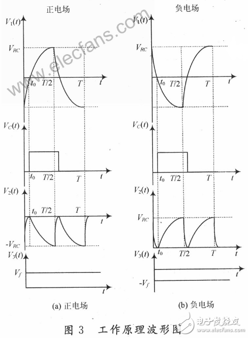
Phase sensitive detection circuit working principleIf the electric field probe is in a positive electric field, the induced voltage signal V1(t) and the synchronous signal VC(t) of the probe are respectively input through the detector of FIG.

When V1(t) is negative half cycle and VC(t) is low level, voltage at point A is negative half cycle, voltage at point B is positive half cycle, analog switch 1 in MC14066BCP is disconnected from switch 3, and analog switch 4 is turned on. Then the output of O4 pin is the negative half cycle of V2(t), and the output of O3 pin is high impedance state; when V1(t) is positive half cycle, Vc(t) is high level, the voltage of point A is positive half cycle, point B When the voltage is negative for half a week, the analog switch 1 and the switch 3 in the MC14066BCP are turned on, and the analog switch 4 is turned off. The output of the O4 pin is in a high-impedance state, and the output of the O3 pin is a negative half cycle of V2(t). During the entire signal period T, the detection output signal V2(t) is always negative half cycle, and the output signal is filtered by the inverse filter to obtain a positive DC voltage signal V3(t), so according to the polarity of V3(t) It can be concluded that the electric field to be measured is a positive electric field, and its working waveform is as shown in Fig. 3(a).

Set in a period T, the angle at which the rotor rotates is φ, that is, the angle at which the small blade rotates is φ, then:

Since the influence of the inductance on the IV conversion circuit is not considered, in actual operation, it should be experimentally performed at -φ/(2π)ωRC{ln[1+exp(-π/(ωRC))]/2)~φ/4 The optimum value of the initial angle φ' is found between. At the same time, since the error of the analog switch is not considered, calibration and compensation by software are also required in the atmospheric field instrument.
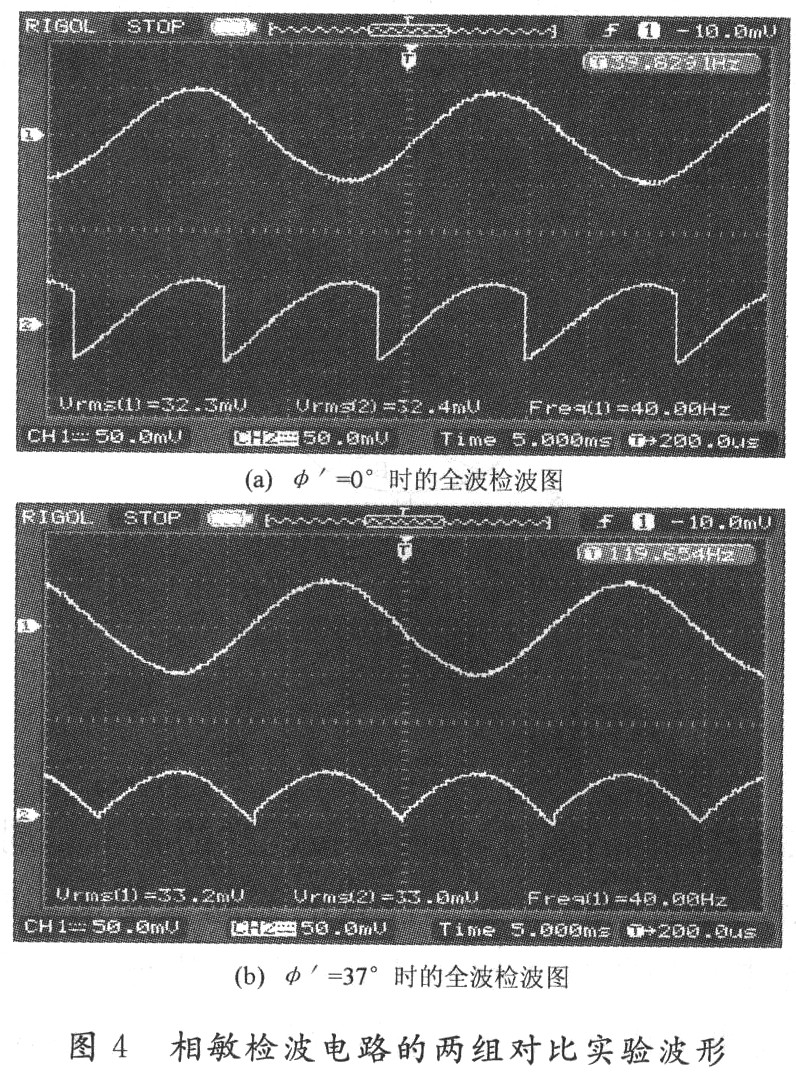
In the design of the electric field meter, the initial angle φ' = 33.23 ° can be obtained according to the formula (5), but φ' = 37 ° is actually selected. Fig. 4 shows the two sets of comparative experimental waveforms of the phase sensitive detection circuit when the measured electric field is -600 V/m, and the initial angles φ' = 0° and φ' = 37° are respectively selected. Waveform 1 is the induced voltage signal after IV conversion, the frequency is 40 Hz, and its amplitude is proportional to the intensity of the measured electric field; waveform 2 is the input signal of the full-wave detection signal output from the analog switch, that is, the low-pass filter. The polarity of the voltage signal is opposite to the polarity of the electric field being measured. By observing the two sets of experimental waveforms, it can be found that when the initial angle φ'=O°, since the weak induced voltage signal V1(t) is different from the synchronous pulse signal Vc(t), the waveform after the full wave detection is still an AC signal. , does not have a single direction, will be filtered out after the low-pass filter, can not get a smooth DC voltage signal, and when the initial angle φ ' is set to 37 °, after the full wave detection is a single positive direction pulsating DC voltage The signal ensures that the weak induced voltage signal V1(t) is in phase with the sync pulse signal Vc(t). Therefore, after outputting a negative DC voltage signal through the low-pass filter, it can be determined that the measured electric field is a negative electric field, thereby realizing accurate identification of the polarity of the measured electric field.
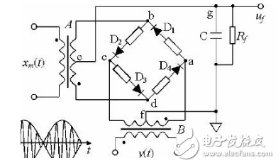
Multifunctional phase sensitive detection circuitThe phase sensitive detection circuit (cooperating with the filter) can reduce the amplitude modulation wave to the original signal waveform and function as a demodulation; and has the ability to discriminate the phase of the signal. A typical diode phase sensitive detection circuit and its input-output relationship diagram are given below. It consists of four diodes D1 to D4 with the same characteristics connected in series in the same direction to form a bridge circuit with additional resistors on the bridge arm for bridge balance. The four terminals are respectively connected to the secondary coils of transformers A and B. The input of transformer A is amplitude modulation wave xm(t), the input signal of B is carrier y(t), and uf is output. The conduction and turn-off of the diode is completely determined by the output of the secondary of B, so the output of the secondary of B is required to be greater than the secondary output of A.

We can follow customers' drawings or design to make Customized wire
harness for various industries: game machine, ATM, POS machine, etc.
Customized wire assembly with AVL components from original manufactures. Also harness with local equivalent componets are workable with short L/T and competitive price, also flexible MOQ.
Medical Wire Assemblies,Medical Alligator Clip Cable,Medical Cable Assembly,Medical Wire Harness,Medical Cable
ETOP WIREHARNESS LIMITED , https://www.etopwireharness.com