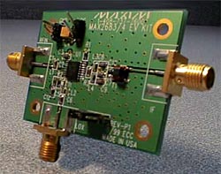
REP022: Frequency conversion from 900MHz to 3.5GHz RF upconverter with 5dB gain and 5dBm IIP3
| Rapid engineering prototypes (Rapid Engineering Prototypes) are the actual circuits that Maxim application engineers build and conduct product testing in the laboratory. They are the starting point for new RF engineering designs. They are not used as evaluation testing tools. |
For more information, wireless product web pages, a quick tour of MAX2683 / MAX2684 data, application technical support

Objective: To develop a circuit using this down-converter IC as an up-converter.
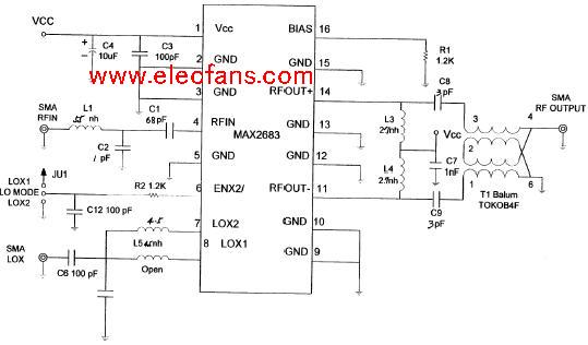
The MAX2684 is used here as an upconverter. Its performance is tested in the 800MHz to 900MHz IF input band (through the RF input pin), using a local oscillator up to 1.7GHz, and the observed output frequency is 3.5GHz (from differential IF output pin). Use a balun to convert the output and connect to a 50Ω transmission line. The measured upconversion gain is 5dB, and the linearity is + 5dBm IIP3. When designing the matching network, a set of S parameters were referenced. This application circuit is considered very successful.
The MAX2684 is a high-performance, low-power downconverter designed for the 3.5GHz wireless data transceiver receiving channel. It has a conversion gain of 1dB, variable IIP3 up to 12dBm, conversion range from 800MHz to 3.5GHz, using low-end LO (approximately 2.7GHz). The MAX2684 has a LO frequency multiplier that is used when inputting a 1/2 local oscillator frequency. It can be switched between basic mode and frequency multiplication mode. The MAX2684 has a minimum operating voltage of 2.7VDC and is packaged in a 16-lead TSSOP.

2.0mm (0.079") Pitch Pin Headers
2.0mm pin headers are board-to-board or PCB to PCB Connectors rated for 250VAC and an industry-leading current of 3.0A. Antenk offers numerous configurations for this pin header. Designed for low-profile applications, this pin header is made from high-temperature thermoplastic and is offered with several means of connections and mounting styles such as through-hole (THM) or surface mount (SMT) and can be in vertical (straight), elevated or at a right angle configuration/orientation
Pin header customization is also available upon your request. The 2.0mm pitch pin header is highly recommendable for signal and low power PC board connections when space is at a premium and when 1.0mm and 1.27mm pitch headers cannot dissipate the required current. In addition, the 2.0mm pitch pin header holds an excellent mating quality that fits with various types of female connectors.
Automotive, Heavy Duty Military and Marine
2.0mm pitch pin headers are for not only suitable for densely packed equipment requiring weight reduction and downsizing but also for automotive connections, built to be robust in tough and harsh conditions.
Battery Connections
Rechargeable battery packs, battery balancers, battery eliminator circuits. Battery connections rely on the ability of the current to pass reliable and solid current. This prevents overheating in the circuit and voltage drop.
Medical Diagnostic and Monitoring equipment
Communications: Telecoms and Datacoms
Industrial and Automotive Control and Test
2.0mm pitch pin (male) headers are offered in either Surface-mount or Through-hole mount termination. At one side of this pin header is a series of pins which can either be mounted and soldered directly onto the surface of the PCB (SMT) or placed into drilled holes on the PCB (THM).
Best used for high-reliability products that require stronger connections between layers.
Aerospace and military products are most likely to require this type of mounting as these products experience extreme accelerations, collisions, or high temperatures.
Useful in test and prototyping applications that sometimes require manual adjustments and replacements.
2.0mm vertical single row header, 2.0mm vertical dual row header, 2.0mm Elevated single row pin header, 2.0mm Elevated dual row pin Header, 2.0mm Right-angle single row header and 2.0mm Right-angle dual row header are some examples of Antenk products with through-hole mount type.
Surface-Mount
The most common electronic hardware requirements are SMT.
Essential in PCB design and manufacturing, having improved the quality and performance of PCBs overall.
Cost of processing and handling is reduced.
SMT components can be mounted on both side of the board.
Ability to fit a high number of small components on a PCB has allowed for much denser, higher performing, and smaller PCBs.
2.0mm Right-angle Dual Row pin header, 2.0mm SMT Single row pin header, 2.0mm SMT Dual row pin header and 2.0mm Elevated Dual Row Pin Header are Antenk`s SMT pin headers.
Soldering SMT pin connectors can be done at a maximum peak temperature of 260°C for maximum 60 seconds.
2.0mm pitch headers may be further classified into pin orientation as well, such as vertical or straight male header or right-angle male header.
Vertical or Straight Pin (Male) Header Orientation
One side of the series of pins is connected to PCB board in which the pins can be at a right-angle to the PCB surface (usually called "straight" or [vertical") or.
Right-Angle Pin (Male) Header Orientation
Parallel to the board's surface (referred to as "right-angle" pins).Each of these pin-types have different applications that fit with their specific configuration.
PCB Connector Stacking
Elevated Pin Header Orientation
Elevated pins aka Stacked Pins or Mezzanine are simply stacked pin headers providing an exact distance requirement between PCBs that optimizes electrical reliability and performance between PCB boards.
Profile Above PCB
This type of configuration is the most common way of connecting board-to-board by a connector. First, the stacking height is calculated from one board to another and measured from the printed circuit board face to its highest insulator point above the PCB.
Single, Dual, Triple and Four Row Number of Rows
For a 2.0mm straight or vertical male pin header, the standard number of rows that Antenk offers ranges from 1 to 4 rows. However, customization can be available if n number of rows is needed by the customer. Also, the number of contacts for the single row is about 2-40 pins. For dual row, the number contacts may vary from 2-80 pins. For triple row, it`s 2-120 pins, while for four-row, it`s 2-160 pins.
Pin Material
The pins of the connector have been designed with copper alloy. With customer`s demand the pins can be made gold plated.
Breakaway design
The pin headers are also equipped with a breakaway design making them fully compatible with their female receptacles.
Custom 2.0mm Pitch Pin Headers
Customizable 2.0 mm pitch pin headers are also available, making your manufacturing process way faster as the pins are already inserted in the headers, insulator height is made at the right size and the accurate pin length you require is followed.
Parts are made using semi-automated manufacturing processes that ensure both precision and delicacy in handling the headers before packaging on tape and reel.
Tape and Reel Packaging for SMT Components
Antenk's SMT headers are offered with customizable mating pin lengths, in which each series has multiple number of of circuits, summing up to a thousand individual part number combinations per connector series.
The tape and reel carrier strip ensures that the headers are packaged within accurately sized cavities for its height, width and depth, securing the headers from the environment and maintaining consistent position during transportation.
Antenk also offer a range of custom Tape and reel carrier strip packaging cavities.
Pcb Pin Header,2.0Mm Male Header,2.0Mm Male Header Pins,2.0Mm Pin Header,0.079in Male Header, 0.079in Pin Header Connector
ShenZhen Antenk Electronics Co,Ltd , https://www.antenkconn.com