Introduction to LIN bus
LIN (Local Interconnect Network) is a low-cost serial communication network used to implement distributed electronic system control in automobiles. The goal of LIN is to provide auxiliary functions for existing automotive networks (such as the CAN bus), so the LIN bus is an auxiliary bus network. When the bandwidth and multi-function of the CAN bus are not required, such as the communication between the smart sensor and the braking device, the use of the LIN bus can greatly save costs. In addition to the basic protocol and physical layer, development tools and application software interfaces are defined in the LIN technical specifications. LIN communication is based on the SCI (UART) data format, using a single master controller / multiple slave device mode. Only use a 12V signal bus and a node synchronization clock line without a fixed time reference. This low-cost serial communication mode and the corresponding development environment have been formulated as standards by the LIN Association. The standardization of LIN will reduce costs for automotive manufacturers and suppliers in developing application operating systems.
Typical LIN bus applications are joint assembly units in automobiles, such as: doors, steering wheels, seats, air conditioners, lights, humidity sensors, alternators, etc. For these cost-sensitive units, LIN can make those mechanical components such as smart sensors, actuators or photosensitive devices widely used. These components can be easily connected to the automotive network and are easily maintained and serviced. In LIN-implemented systems, analog signals are usually replaced with digital signals, which will optimize the bus performance. The use of LIN in the following automotive electronic control systems will achieve very perfect results:
LIN node hardware design
1 LIN interface overall design
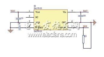
The LIN node hardware mainly includes the LIN interface circuit part, the control input part, the display circuit or the load drive output, etc., where the LIN interface is the core of the node. The LIN interface circuit with Microchip's PIC16F87 as the controller, TJA1020 as the LIN transceiver, and SA57022 as the switching power supply is shown in Figure 1. The power on and off of the SA57022 power output is controlled by the LIN transceiver through the INH pin.

Figure 1 LIN interface schematic
Because the master node needs to provide a clock reference for the slave nodes in the network, an external crystal oscillator is configured for the PIC16F87 in the master node. In the slave node, the slave node can calibrate its baud rate through the synchronization field in the frame header sent by the master node, so it can save the external crystal oscillator and use the built-in RC oscillator of PIC16F87.
2 LIN transceiver application design
TJA1020 is a LIN transceiver. It is the interface between the LIN protocol controller and the LIN transmission media. It is the core device of the node. It is responsible for the bus waveform adjustment and level conversion when receiving and sending data, and the realization of multiple working modes of the node. The TJA1020 integrates the on-chip slave-side resistors according to the LIN physical layer specification. There is no need to connect the slave-side resistors in the slave node application. In the master node application, as shown in Figure 1, between its INH pin and LIN pin Connecting the host-end resistor and diode in series can improve the driving capability of the bus, and make the node automatically enter the sleep state when the bus is shorted to ground, reducing current consumption.
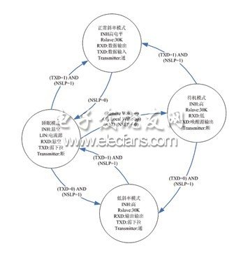
The LIN node constructed with TJA1020 as the transceiver has four working modes: normal, low slope, sleep, and preparation, in order to reduce power consumption and electromagnetic radiation as much as possible. The node status and mode conversion between various modes are shown in Figure 2.

Figure 2 Node status of working mode and switching between modes
LIN node software design
1 LIN host node software design
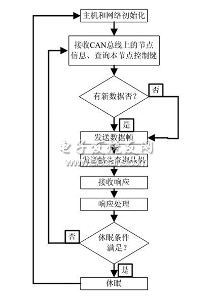
The LIN host node performs frame processing and LIN network communication management functions. The program flow is shown in Figure 3.

Figure 3 Host program flow
The LIN specification specifies that the sync interval field is at least 13 consecutive dominant bits (low level). LIN communication is based on the universal UART / SCI interface, byte transfer uses 8N1 encoding, and such an explicit sequence cannot be directly generated.
The normal communication baud rate of the bus is 9.6k, and the slave node always works at this baud rate. The master node reduces the baud rate to 4.8k when it needs to send the synchronization interval field, and sends 0x00, then it works in 9.6k wave The special rate slave node will detect 18 consecutive dominant bits to judge the arrival of a new message frame. The host node restores the baud rate to 9.6k after sending the synchronization interval field.
2222Bossgoo(China)Tecgnology.
(Bossgoo(China)Tecgnology)8866 , https://www.cn-gangdao.com