Introduction: Capacitive touch sensing is a popular technology for implementing intuitive user interfaces (UIs) in a variety of electronic applications such as smartphones, tablets, LCDs and LED TVs. Touch buttons are quickly replacing traditional mechanical buttons. However, unlike mechanical buttons that provide user tactile feedback, touch buttons require additional components to provide feedback. LEDs are widely used to achieve visual feedback and provide backlighting for touch-based UIs.
Some applications require more visual effects in addition to simply turning the LEDs on and off. For example, a laptop can flash the power LED while the device is in standby mode, and the brightness changes in light and dark, creating a so-called respiratory effect, which is one of the many LED effects (fade or flicker) used in the device. Advanced LED effects combined with capacitive touch buttons increase the aesthetics of the system and improve the user experience.
We often want to use the same system-on-a-chip (SoC) to implement multiple features, reducing BOM costs. In a four-part series, we'll cover different aspects of capacitive sensing and LED lighting with the same SoC, including:
â— We will briefly introduce the different LED lighting technologies used in capacitive sensing UI applications through practical use cases.
â— Pulse width adjustment ( PWM ) is one of the common techniques for achieving LED effects. We will analyze the different LED effect implementations using PWM technology to explore how to choose the right SoC.
â— Integrating multiple features in the same SoC is certainly challenging. To ensure the high level of design, you must address these challenges. Common challenges we will discuss include crosstalk between LEDs and capacitive sensors, drive strength capabilities, LED load transients that cause noise inside the capacitive sensing subsystem, and avoidance methods.
â— Power optimization is very important for any electronic system. We will discuss low-power design considerations for applications that require LED effects.
LED effect
Efficient user interface design requires some kind of user feedback with capacitive touch buttons. When the user presses the mechanical button, the mechanical button itself has a tactile feedback function. However, capacitive buttons do not provide this tactile feedback. Therefore, the UI using capacitive touch buttons can take different forms of feedback, including vision, sound effects, touch, and the like. Depending on the user interface design, a number of different types of feedback can also be combined. Among these feedback types, visual feedback with LEDs is a common choice. Here we will introduce some different types of LED effects and their use cases.
Sensor state driven LED control
In order to improve visual feedback to the user or to mimic mechanical switches, the LEDs can take a variety of different control methods in the firmware. Some common methods include:
1. LED switch
This is the simplest type of LED effect and is often used to display touch status. The LED is located behind the sensor conductor piece as a backlight. When there is a touch, this LED illuminates to provide illumination for the button, and the LED turns off when there is no touch. The application example is a menu or a back button of an Android phone such as the Samsung Galaxy S4.
2. Flashing
TV manufacturers typically offer standard remote controls for different models of television. Some buttons on the remote may not support some models of TV. In this case, if the touched button is invalid, the LED flashing backlight effect can be used to prompt, which is achieved by periodically switching the LED.
3. Switch
Imagine that the room lighting is controlled by a mechanical switch. When the switch is pressed once, the light will turn on. As long as the switch continues to remain in this state, the light will remain on. Press the switch again and the light will go out. The switching characteristics are similar to this mechanical switch. When the capacitive button is touched, the corresponding LED will illuminate. Even if the user leaves the button, the LED will remain lit. If the user touches the button again, the LED will turn off. That is to say, in the rising edge of each capacitive sensor state, the output state will switch its state, as shown in the figure below. CS0 reflects the sensor status and GPO0 reflects the LED status.

Figure 1: LED switching
4.LED on time
Usually for capacitive buttons, the LED is directly under the button and illuminates from the center. When the user puts his finger on the button, the LED will be hidden. In this case, if the user's hand has just turned off the LED light from the button, the user may have difficulty closing the button operation. To this end, we can keep the LEDs "on" for a short period of time after the end of the touch, thus providing users with better visual feedback. This feature is called the LED turn-on time, as shown in Figure 2.

Figure 2: LED On Time
Advanced LED effect
Many advanced effects can be achieved by changing the brightness of the LED lights. Imagine that the front panel of a TV can be operated by touch buttons, including adjusting the volume. The picture below is an example of a TV panel.

Figure 3: TV front panel with backlit touch buttons
The panel is all black and has a bright surface that matches the corner design and aesthetic requirements. In order to allow the user to control in the dark, the button is always lit with a low-brightness LED. If you touch the button, the brightness of the LED will increase.
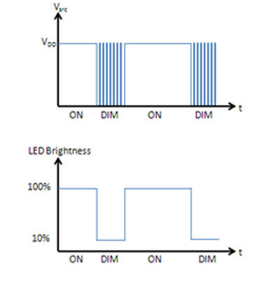
PWM is a key technology in LED brightness control applications. By changing the duty cycle of the PWM output, we can adjust the LED brightness as shown in Figure 4, so that the brightness of the user interface corresponds to the button status and ambient light conditions. In fact, changing the brightness is the basis for advanced effects such as breathing, fades and fades. We will introduce PWM design parameters and a variety of different implementations in the second part.

Figure 4: LED brightness control
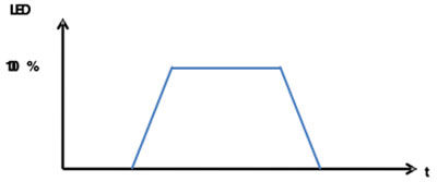
1.LED fades in and out
Fade is to let the brightness change step by step. Low brightness becomes high brightness called fade in, the opposite is called fade out. By gradually changing the duty cycle through a series of small steps between different LED states, we can achieve a fade effect (see the figure below).

Figure 5: LED fades in and out
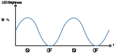
2. LED breathing
At the beginning of this article, we briefly introduced the breathing effect through the power button of the laptop. Continuously increasing or decreasing the duty cycle between the two stages can cause the LED to form a "breathing" effect, as shown in Figure 6. The power button in standby mode supports the breathing effect to tell the user that the power button is active and can operate.

Figure 6: LED Breathing
Some vendors have introduced configurable devices that implement these advanced LED effects and capacitive sensing on a single chip, such as Cypress's CY8CMBR2110 and CapSense MBR3.
In this section, we introduce the different LED lighting technologies used in capacitive sensing UI applications through practical use cases. In the second part, we will introduce different ways to implement PWM.
Crossarm-Mounted Stringing Block
Ningbo MARSHINE Power Technology Co., Ltd. is a professional engaged in the development, design and manufacture of power engineering construction equipment and tools.
MARSHINE company produces circuit construction tools, including foundation construction, tower group lap. Wiring structure. Cable construction, cable construction, mobile knife mill, insulated overhead cable and high voltage Cable Stripper, all kinds of aluminum alloy pull rod, guide rail, grounding device, high strength shackle, Ratchet Wrench and pointed wrench, double hook tight line device, lifting pulley, nylon wheel and aluminum wheel, punching machine ect.
MARSHINE continues to carry forward the enterprise spirit of "integrity, development, innovation" and strive for the prosperity and development of the electric power industry.
Welcome to contact MARSHINE and reach cooperation, thank you!
Crossarm Mounted Stringing Blocks,Angled Crossarm-Mounted Stringing Block,Angled Crossarm -Mounted Stringing Cable Pulley Blocks,Universal Crossarm Mounted Stringing Blocks
MARSHINE , https://www.puller-tensioner.com