Cypress's PSoC microcontrollers are easy to use, flexible and have a range of cost-effective reprogrammable analog and digital resources. With these features, various creative designs can be realized, such as using an on-board host processor to serially program PSoC. This method is used to install or update the firmware on site or even completely reprogram the PSoC to perform other functions.
The HSSP code example was created by Cypress to help system designers start creating their own serial programming software. Designers must minimize the modification of this code to ensure compatibility with a particular host programmer. This code example only covers the CY8C20xx6A family of PSoC devices and is highly abstract. For more information on serial programming, refer to the ISSP programming specification. This article outlines the implementation method. The details of the protocol and the meaning of each vector are proprietary information, which are omitted on purpose.
Overview
PSoC devices can be programmed in two different modes: reset mode and restart mode. Reset mode is the preferred programming mode and is only used when the system is powered externally. In this case, the XRES pin on the target PSoC will switch at the end of the process, causing it to exit programming mode and resume normal operation. In restart mode, the host microprocessor switches the PSoC power switch.
In both programming modes, the host requires three I/O pins. The serial data (SDATA), serial clock (SCLK), and external reset (XRES) pins are in reset mode, and the SDATA, SCLK, and PSoC power (PWR) pins are in power cycling mode. These pins are controlled by software.
The SDATA pin on the host processor must be bidirectional. The host must be able to change the properties of this pin in order to use it to signal PSoC, release it to the High Z state, and read the signal from that pin.
Attribute selection
The designer must set the following two attributes: label and description. To make this setting, you can comment or uncomment some #defines in the ISSP_DIRECTIVES.H file. These #defines are labeled "User AttenTion Required" and are very obvious and easy to find. You can also do a page search to find a single tag. The description of each property and its label will be listed below the property:
Property: Programming Mode
Label: PROGRAMMING MODE (programming mode)
Note: If you are using restart mode, comment #define. If you are using reset mode, you should uncomment the #define statement.
Attribute: Target PSoC device
Label: TARGET PSOC (Target PSOC)
Description: Select the target CY8C20xx6A PSoC in this section. In any given case, only one device can be enabled and all other devices should be commented out. Low-level driver modifications.
The designer bases the host-specific code to operate on the pins involved in programming the target PSoC. These APIs can be found at ISSP_DRIVER_ROUTINES.C and are labeled "Processor Specific" and "User AttenTIon Required".
■Port Bit Mask: The four port bit masks must be adjusted for the specific host processor being used. Note that although four bits are to be set, depending on the programming method used, only three bits are used during programming—SDATA, SCLK, and XRES in reset mode; SDATA, SCLK, and in power cycle mode. PWR.
■Delay(n) function: Adjust this function to keep each iteration of the while loop at least 1μs. There is usually no upper limit to the cycle time. However, the longer the cycle time, the longer the programming time for the target. For example, if the host microprocessor is also PSoC, each iteration is approximately 1μs and the overhead is 3μs. Therefore, the function will produce a delay of n+3 μs, where n is the parameter passed to the function. To adjust the host processor's latency, modify #define in ISSP_DELAYS.H.
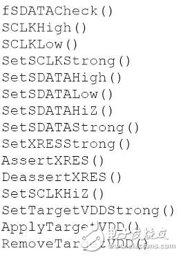
â– Port bit manipulation functions: These functions will control the host pins to generate the signals required for PSoC programming. They can drive the pin output high or low, can also release the pin to the High Z state. The following is a list of these functions. The purpose of most of the functions is self-explanatory, but there are records in the code. Instructions are also provided in the appendix.

Load data into RAM buffer
The HSSP code will sequentially fetch data from the 128-byte buffer for PSoC flash block programming. This process begins with the lowest block address. After programming the first block, the same buffer will be used to program the subsequent flash block.
Designers must write code based on the data source (USB, RS-232, SD card, etc.) to fill this buffer. For the specific host processor used, the following two functions should be written: LoadProgramData() and fLoadSecurityData(). These functions can be found in ISSP_DRIVER_ROUTINES.C and are labeled "Processor Specific" and "User Attention Required." In the original state, these functions call two helper functions and load dummy test data into the buffer for debugging. In the final version, delete or comment out these call statements.
Modify flash block order or number
In some cases, certain areas in the flash memory must be programmed. For example, areas dedicated to storing features, calibrations, or firmware upgrades in the field. These features are usually implemented through EEPROM user modules. However, in some cases, if code space is limited, these features can be written directly in PSoC to save code space.
You can change the starting address of the target block and the programming order of the blocks. The above operation does not cause any problem because each programming sequence contains a block address. However, keep in mind the following points:
â– If the programming loop is modified, the same change must be applied to the verification loop, otherwise the verification will fail.
■The code accumulates the checksum during operation and checks the checksum against the entire flash memory as of that time. If you are programming only one area of ​​the flash memory, the variable iChecksumData should be set accordingly.
Use built-in test points for verification
One of the most critical factors for successful host source programming is getting the correct erase and write pulse widths. To help you with this process, several test point (TP) calls are implemented at important locations in the program. To enable this debug mode, uncomment the USE_TP #ifdef in ISSP_DRIVER_SOUTINES.H. There are several functions related to the debug mode, which are similar to the pin operation functions mentioned earlier in this article. System designers must provide host-specific code to drive the pin to output high, low, or switch pins.
The correct debugging process requires monitoring of the TP and SDATA lines, and the erase and programming pulses must be measured. The best way to achieve this is to use a dual trace oscilloscope and trigger on the rising edge of the TP channel to put it into single-sequence mode.
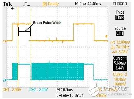
The erase pulse width is measured from the end of the data burst to the end of the TP falling edge, as shown in Figure 1. Please note that the rising edge of TP is not in line with the end of the data burst. However, due to the delay overhead between when the TP pin is driven high and when the host starts sending data, the rising edge of TP is expected to line up.

Figure 1. Measuring erase pulse width
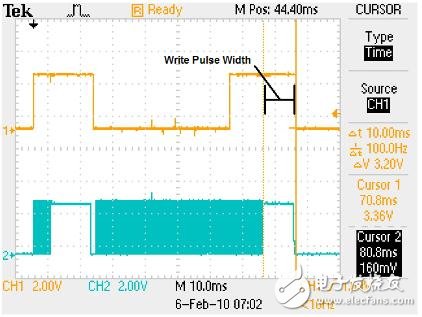
The programming pulse width is also measured from the end of the data burst until the end of TP falls. Figure 2 shows the program pulse width measurement. Like the erase pulse width, the rising edge of the TP signal and the end of the data burst are not in a line.

Figure 2. Measuring Write Pulse Width
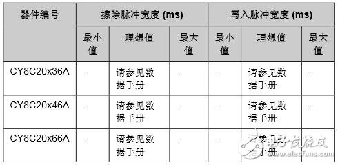
Table 1 summarizes the ideal erase and write pulse widths for various PSoC devices. The measured value must be in the range of -3% to +15% of the ideal value. Failure to meet this requirement will result in erroneous programming and adverse effects, such as shorter flash data retention times than specified specifications, and fewer flash erase and write cycles than expected.

Table 1. Erase and Write Pulse Widths for CY8C20xx6A PSoC
limit
The comments at the beginning of main.c contain useful important information that system designers should consider carefully. These notes explain some of the limitations of the HSSP code; however, the following is a brief summary.
■Serial programming can only be performed in the temperature range of 5°C and 50°C.
â– The HSSP program does not support voltages below 1.8V.
â– The programming process is only done within one voltage range. If the initial device voltage is 5.0V, the entire process must be completed within 5.0V.
â– There is an upper limit to the frequency of SCLK. This frequency is specified in the "AC Programming Specifications" section of the device data sheet and is marked with the symbol FSCLK.
Hydraulic crimping compressors of various type including petrol, diesel and electric hydraulic Power Unit, which is coupled with hydraulic crimping head and hydraulic Crimper.This Hydraulic Crimping Tool only can be working by both motorised oil pump and hydraulic compression head, both of them are small volume,light weight and long service life,it is working with fast speed that average working stroke can be within 2-3 seconds,thus can easily increase conductor connecting efficiency.It is specially used for crimping cable and conductors to be connected tightly.Besides,it is also used for busbar processing machine such as hydraulic bender,puncher,cutter,etc.we are a professional Chinese exporter of Hydraulic Conductor Crimper and we are looking forward to your cooperation.Yangzhou Qianyuan Electric Equipment Manufacturing & Trade Co. Ltd is specialized in manufacturing and trade of electric power line transmission tools. Our main products are Anti-twisting Steel Wire Rope,Stringing Pulley,Hydraulic Crimping Compressors,Engine Powered Winch,Motorised Winch,Wire Grip,Gin Pole,Cable Stand,Mesh Sock Grips,Cable Conveyor,Lever Chain Hoists and so on,which are mainly supplied to power companies,railroad companies and other industry fields.
All our products are certified by China National Institute.
To assure the quality, we will do 100% inspection for raw material, production procedure, packing before shipment,
so we do have the confidence to supply customers with high-quality and high-efficiency products.
"Customer satisfaction" is our marketing purposes, so we have extensive experience in professional sales force,and strongly good pre-sale, after-sale service to clients. We can completely meet with customers' requirements and cooperate with each other perfectly to win the market.Sincerely welcome customers and friends throughout the world to our company,We strive hard to provide customer with high quality products and best service.
hydraulic power pack, hydraulic crimping tools, hydraulic hose crimper, hydraulic crimping head, hydraulic crimping machine
Yangzhou Qianyuan Electric Equipment Manufacturing & Trade Co.Ltd , https://www.qypowerline.com