Nowadays, with the rapid development of the Internet of Things, the application of each frequency band has reached the extreme, which leads to mutual interference between different modules, and the requirements for filtering and anti-interference are continuously improved. How to avoid co-channel interference has become a problem that plagues many engineers.
To solve the problem of co-channel interference, both software and hardware can be used. This paper mainly provides solutions for co-channel interference from the perspective of hardware design.
From a hardware point of view, to avoid co-channel interference, you can increase the available bandwidth. Adding bandwidth means that there are more choices in frequency hopping, and the distance between channels is larger to avoid mutual interference. Greatly reduced the difficulty of software design.
In practical applications, factors affecting the bandwidth of the wireless module are LNA input impedance, PA output impedance, filter impedance, and antenna impedance. The former two users can only match according to the parameters given by the original factory, and the impedance of the antenna is to select the corresponding model according to the actual application scenario, so the impedance matching of the filter is the key to the circuit design.
We all know that the transmission power can reach the maximum when impedance matching, but in actual design, it can only reach the impedance matching of a certain frequency point, which is not in line with engineering applications. Equalized power transfer over a range of frequencies is more important than maximizing transmission power at a certain frequency. The signal output is not concentrated on a certain frequency point, but the balanced coverage of a wide frequency range not only ensures that the module has a higher fault tolerance rate when applied, but also ensures consistency in mass production.
There are many filters available on the market for the 400-500MHz frequency. Here we have selected two of the most typical filters: Butterworth and Chebyshev, comparing their port impedances at different frequencies, thus The bandwidth of the filter is derived, and finally the most suitable filter for wireless communication is selected.
We did the following experiments. Figure 1 and Figure 2 show two 5th-order 600MHz low-pass LC filters simulated by ADS. Figure 1 shows the Butterworth filter and Figure 2 shows the Chebyshev filter.
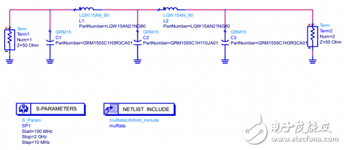
Figure 1 Butterworth filter topology
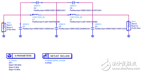
Figure 2 Chebyshev filter topology
Figure 3 and Figure 4 correspond to their port impedance and standing wave ratio, respectively.
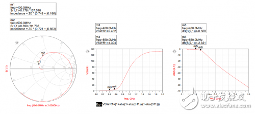
Figure 3 Smith, VSWR and S21 of Butterworth filter
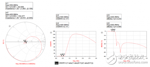
Figure 4 Smith, VSWR and S21 of the Chebyshev filter
It can be clearly seen here that in the Smith circle, the impedances of the two filters at different frequencies are not the same, the Butterworth filter is accompanied by an increase in frequency, the impedance deviates from the matching point; and the Chebyshev filter has resonance. The circuit causes a sudden change in impedance, so the impedance will vary around a small range around the matching point, which results in a Chebyshev filter having more available frequency bands than the Butterworth filter.
The LM400T module uses the Chebyshev filter topology as a model to design the filter circuit. The channel can cover 400MHz~525MHz, and the output power is kept above 18dBm, which is enough to meet the channel division requirements.
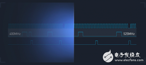
When multiple groups of modules work simultaneously, multiple channels can be divided, so that different groups of modules can communicate under different channels, and communication between modules is not affected by dividing channels, which avoids the same The effect of frequency interference.

Axial Metallized Polypropylene Film Capacitors
Power Supply Capacitor,Filter Power Capacitor,Hv Film Capacitor,High Voltage Metallized Film Capacitor
XIAN STATE IMPORT & EXPORT CORP. , https://www.shvcomponents.com