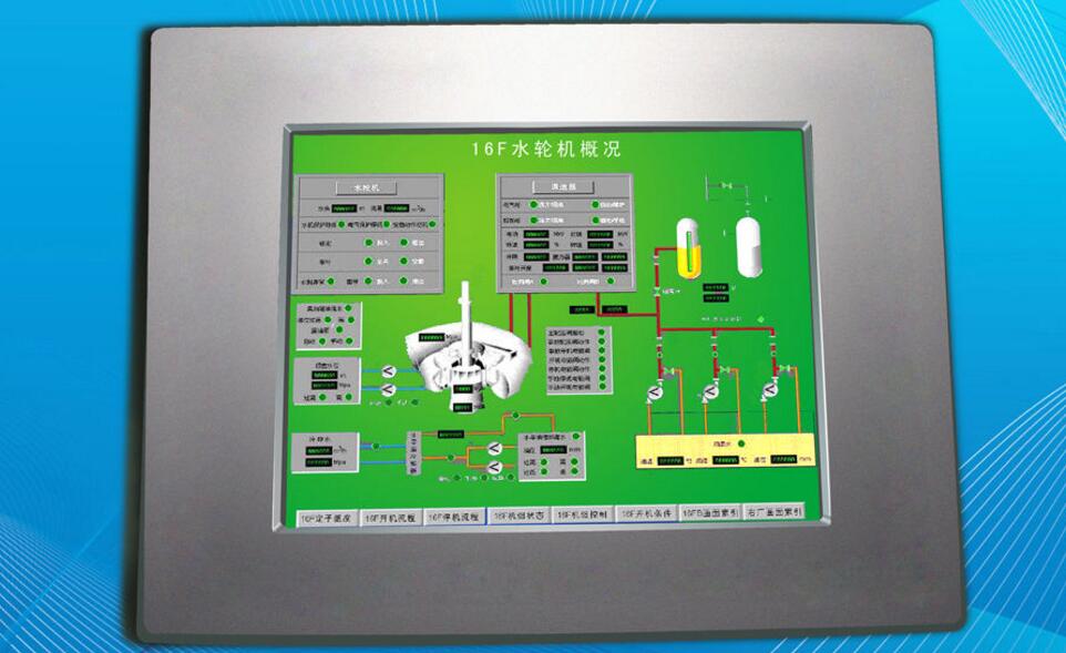
Human-machine interface refers to the field in which people and machines contact or interact with each other in information exchange and function, or the interface between the human and the machine, information exchange, functional contact or mutual influence, referring to the hard contact and soft touch of people and machines. This joint surface includes not only the direct contact of the dotted line surface, but also the space for the long-distance information transmission and control. The human-machine interface is a central part of the human-machine system. It is mainly studied and proposed by the sub-discipline safety ergonomics of safety engineering, and has passed safety engineering equipment engineering, safety management engineering and safety system. Engineering to study specific solutions and measures to measure safety ergonomics. It transforms between the internal form of information and the form that humans can accept. There are human-machine interfaces in all fields of human-computer information exchange. It is widely used in industry and commerce. It is simply divided into "Input" and "Output". Input refers to the operation of machinery or equipment by people, such as handles, switches, doors, commands. (Command) release or maintenance, etc., and output refers to notifications from machinery or equipment, such as faults, warnings, operating instructions, etc. Good human-machine interface will help users to be simpler, more correct, and more The rapid operation of the machine can also maximize the performance of the machine and prolong its service life. The human-machine interface on the market is narrowly defined in the user-friendly operating interface of the software.
How to use the human-machine interfaceClearly monitor the mission requirements and select the appropriate HMI product;
Edit the "project file" with the screen configuration software on the PC;
Test and save the edited "project file";
The PC is connected to the HMI hardware and the "project file" is downloaded to the HMI.
Connect HMI and industrial controllers (such as PLCs, meters, etc.) to achieve human-computer interaction.

The human-machine interface of the project realized by the single-chip microcomputer is relatively simple. If it is LED display, it should be based on the number of LEDs to select a simple, clear, user-looking prompt; the number of data displayed should fully consider the technical requirements of the user.
Analyze programming difficulties and technical solutionsEven a skilled programmer will encounter some difficulties during the programming process. In order to complete the program design smoothly, the framework of the whole program should be analyzed according to the functions and program flow completed by the program, and the difficulties of the whole program should be located according to the skills mastered by the program, and then the best algorithm can be found. For example, for a slightly larger project, the programming of the keyboard scan and display should be a difficult point in microcontroller programming.
(1) Both the keyboard scan and the display process are closely related to the hardware part.
To select the keyboard for the chip selection signal, it is necessary to find out whether the MCU chip is high-level strobe or low-level strobe; after strobing the keyboard, it is also necessary to read back the state of the keyboard. Anti-shake processing is also performed on the read-back keyboard state; if the keyboard is jittery, the read-back data is discarded, and the keyboard state is re-read; if it is determined that the keyboard is pressed, the key value can be processed; the processed key value is sent to display or Used as other. It can be seen that each of the above processes deals with the hardware circuit.
(2) The algorithm involved in keyboard scanning and display is more complicated
Because the process of scanning the keyboard is to traverse each button, identify the jitter, identify whether the button is released, etc.; in addition to delay the appropriate time to read the key value again. The display process also traverses each digital tube or liquid crystal character; in the process of looking up the table, the display process uses a more complicated loop traversal algorithm.
(3) The distinction between numeric keys and function keys
It is the number key to send the display, the function key is transferred to the corresponding function subroutine, and the combination of the two constitutes a more complicated scatter program. The MCS51 MCU has a ready-made loose rotor program for reference. The PIC can be applied with reference to the MCS51's loose rotor program.
The above three points are the difficult part of MCU programming, and should be found out carefully before programming. Through analysis, all the possible difficulties are found out and the corresponding algorithms are found out, which is correspondingly smooth in the process of writing later.
programming
After the above preparations are completed, you can start writing the program. Because there is a clear program flow, with sufficient information, the difficulties that may be encountered basically find a solution; thus, the preparation is sufficient in advance, even if it is difficult to solve in the later process of writing, it is easier to solve . This saves a lot of time, so that you can calm down and carefully write programs according to the program and process. In addition, generally write a function program to debug, after writing another function code, this can prevent the mutual influence of debugging after all the code is written, so that you can figure out which part of the program has problem.
Program debugging
The debugging process of the program is a relatively complicated process, and some require a high degree of skill and certain methods. General programming software provides basic methods such as single-step, single-step crossing, breakpoint, and running to the cursor. Generally, mastering these basic methods can solve most problems. After a long period of debugging practice, you can naturally master certain debugging skills, that is, practice makes perfect.
Man-machine interface simple programming example 1, principleThe beauty of the AcTIveX control is that controls and applications always interact harmoniously. The AcTIveX control provides three basic mechanisms for interacting with applications: properties, methods, and events. The user controls the controls and develops the program in three parts. Attributes describe the current state of the control and affect the display and behavior of the control. The property values ​​are stored in the variables of the control. The method is a function defined in the control (FuncTIon). The use of the method is related to the function provided by the control. It usually affects the control itself or its behavior. The role of most methods is also affected by the properties of the control at that time. An event is a notification event generated by a control in certain situations. The event is passed to the control application to execute an event handler associated with the event in the program.
The following examples illustrate how to use the DAQBench control to create a human-machine interface and use the AcTIveX control of the ADLINK data acquisition device for analog signal processing.
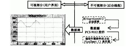
We assume that a program is divided into two parts: the visible part (the interface that displays the operation in the foreground) and the invisible part (the thread that works in the background). The display interface of this program is very simple, there is only one drawing control and one exit button. The background work is to generate sampling data by using a virtual PCI-9112 multi-function data acquisition card (no need to install a real board). The program flow is shown in Figure 1. At the beginning of the program, the method StartContAI of the PCI-9112 control is called to activate the continuous AI. When the sampling is completed, the event AiHalfReady 0 of the PCI-9112 control is automatically activated. In the event response function, the call is made. The PlotChart 0 method of the drawing control transfers the collected data to the drawing control. This way, we can continue to see the sampled data on the screen until the program exits. There are only two statements in the entire program that require keyboard input, and the rest of the work is done with a mouse click. From this app you can feel how easy it is to do data acquisition with DAQBench's ActiveX controls.

Figure 1 program schematic
2, programmingThe following step will be step by step to explain how to use DAQBench's ActiveX control to complete the data acquisition application under Microsoft Visual C++ 6.0.
2.1 Establishment of the program frameworkUse Visual C++'s MFC AppWizard to build a dialog-based program framework.
Create a new project via the File" New menu command, which will open the New dialog. In the Projects page, select the [MFC AppWizard(exe)] project type and enter the project name in Project name: MZR point 0K.
In the Step 1 dialog box, select the [Dialog based] option and click Finish.
In this way, the AppWizard builds a new project and program framework and automatically opens the program dialog in the dialog editor.
2.2 Loading the DAQBench ControlThe steps to add the required ActiveX controls to the Control Toolbar are as follows:
(2) Select the drawing ActiveX control (file name) DAQBench DChart Control—(ADLINK), click the Insert button, and use the mouse to select OK in the subsequent dialog box to accept the default class name and file name.
(3) Select the data acquisition ActiveX control (file name) NuDAQ PCI-9112 Control-(ADLINK), click the Insert button, click the OK button, click the OK button, accept the default class name and file name.
(4) After adding, return to the Components And Controls Gallery dialog box and click the Close button.
In this way, in the control toolbar of the dialog editor, the drawing control DAQBench DChart Control and the data acquisition control NuDAQ PCI-9112 Control are added, which can be easily added to the dialog box.
2.3 ProgrammingOnce you've added controls to your control's toolbar, you're ready to use the controls when designing your application's user interface. Developers can use the dialog editor to place controls on the dialog. The specific steps are as follows:
Delete the static text control with the TODO message on the form and remove the OK button.
Click the DChart button at the bottom of the Controls toolbar and place it in the dialog with a mouse click. The ActiveX control can be inserted into the dialog like a standard Windows control and can be repositioned and resized.
Select the PCI-9112 button at the bottom of the Controls toolbar, place it in the appropriate location in the dialog box, right-click on the PCI-9112 control in the dialog box, and select Properties from the menu that opens. Property page dialog for various property fields. Through the property page dialog, you can set this particular control. The specific values ​​are shown in Table 1.

Table 1 Control NuDAQ PCI-9112 Control Property Settings
Before a user writes a program using a control, first set a variable name for the control. Set the corresponding variables for the drawing control and sampling control: Open the MFC Class Wizard dialog with the shortcut key Ctrl+W, set the Class name to CMZRDlg in the Member Variables tab, and add Variables? The button adds a variable to the control identification number in it. The definition of the variable is shown in Table 2.

Table 2 corresponding control variables in the dialog box
To define the event handler for the PCI-9112 control, use the shortcut Ctrl+W, in the MFC Class Wizard window, press the Message Maps tab and select the IDC_PCI9112CTRLI control in the Object Ids field, select AiHalfReady in the Messages field, and click the Add Function button. Add the AiHalfReady message response function of the data collection control, accept the default function name, click the Edit Code button to locate the function, and add the following code:
Void
CMZRDlg::OnAiHalfReadyPci9112ctrl1(VARIANT FAR*ScaledData, VARIANT FAR*BinaryCodes)
{
//TODO:Add your control notification handler code here
m_Chart.PlotChart(ScaledData);// Pass the sampled data in ScaledData to the drawing control.
}
Start the data collection function in the initialization function:
Navigate to the dialog initialization function void CMzRDlg::OnInitDialog() and return TRUE at the end of it; add the following statement before the statement
BOOL CMZRDlg::OnInitDialog()
{
CDialog::OnInitDialog();
(1) Select Project > Add To Project 》 Components And Controls? Project, then, in the dialog that appears, double-click the Registered ActiveX Controls directory entry with your mouse. This will open a list of ActiveX controls that have been installed and registered on the computer. Select and insert the required ActiveX controls into your project and control toolbar.
/TODO :Add extra initialization here VARIANT Filename;
m_Pci9112.StartContAI(Filename);//Active continuous
Return TRUE; //return TRUE unless you set the focus to a control
}
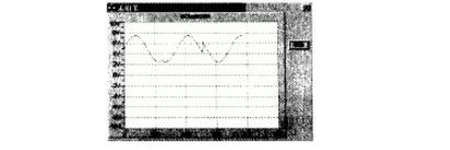
2.4 Program testingRun the program directly in Developer Studio by pressing Ctrl_F5. The result is shown in Figure 2.

Figure 2 results
Development environment: This article assumes that you have installed Visual C++ 6.0 and DAQBench and PCIS-OCX.
The DAQBench and PCIS-OCX software can be downloaded from the ADLINK website (http://.com/download area/software.htm).
12V100Ah Lithium Ion Battery,Deep Cycle Solar Battery,2V 100Ah Lifepo4 Battery,12V 100Ah Lifepo4 Battery Pack
Jiangsu Zhitai New Energy Technology Co.,Ltd , https://www.zhitainewenergy.com