Almost no system has no input/output devices, as large as the display, as small as the led light, and touches the button. As a system, the performance of input and output devices plays an important role in order to work stably. In this experiment, Xiaomei Ge officially stepped into the door of basic peripheral driver development through an independent button test.
First, the purpose of the experiment
The jitter detection experiment of 4 independent buttons is realized, and the flipping of the 4 LED lights is turned off by 4 independent buttons.
Second, the experimental principle
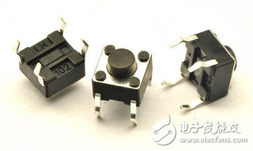
Most of the buttons commonly used in actual systems are light touch buttons, as shown in Figure 2-1. The inside of the button consists of a spring piece and two fixed contacts. When the spring piece is pressed, the two fixed contacts are closed and the button is closed. The spring piece is released, the two contacts are disconnected and the button is disconnected. According to the mechanical characteristics of the button, when the button is pressed, there will be a period of instability for a period of time. During this period, the two contacts are sometimes turned on and sometimes turned off, which we call jitter, when the button is pressed After the next 20ms, the two contacts can be in a stable closed state, similar to when the button is released. And our FPGA works at very high frequency. Any small jitter can be easily captured when the button is turned on or off. If you do not distinguish between each closing or opening as a button event, then it is bound to be A keystroke will be recognized by the FPGA as many keystrokes, resulting in reduced system stability.

Figure 2-1 Touch button physical map
The approximate waveform of a button press is shown below:

Therefore, what we need to do is to filter out the 20ms unstable waveform that exists when the button is pressed and released.
Third, the hardware design
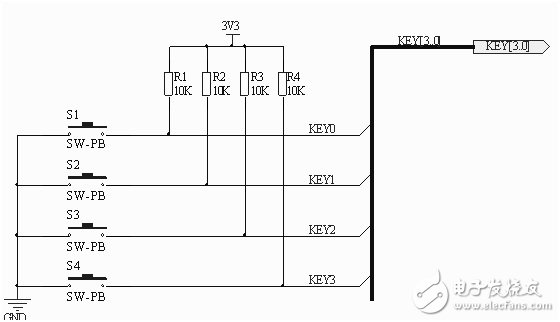
The independent button belongs to an input device, and the IO port connected to the FPGA is connected with a 10K pull-up resistor. When the button is not pressed, the FPGA detects a high level; when the button is pressed, the IO port of the FPGA is pressed. Will present a low level. Therefore, the essence of button detection is to read the level on the IO of the FPGA.

Figure 3-1 Typical circuit of independent button
Fourth, the architecture design
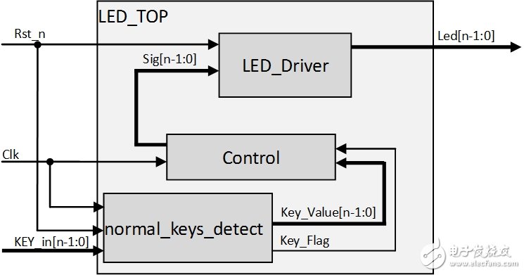
This experiment consists of a total of four modules, which are LED driver module, independent button detection module, control module and top-level module. The architecture is as follows:

Figure 4-1 Organization chart of led experiment module
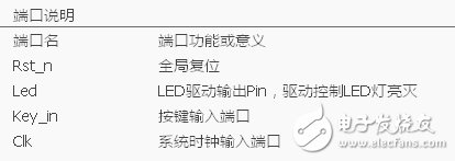
It can be seen from the figure that this experiment has n output ports, corresponding to driving n led lights. n+2 input ports, corresponding to n key inputs and one clock input and one reset input. The detailed port name and its meaning are as follows
Table 4-1 Description of the independent button detection experiment port 
Because there are connections between modules, there are some internal signals. The following table shows the names and function descriptions of internal signals.
Table 4-2 Description of internal signal of independent button detection experiment 
Tension Pressure Laod Cell,Tension Load Cells,Tension Force Sensors,Tension Sensor Load Cell
Xiaogan Yueneng Electronic Technology Co., Ltd. , https://www.xgsensor.com