Abstract: This application note provides the general hardware configuration and software routines for the Dallas I²C interface real-time clock. This routine is applicable to RTC using BCD code time and date format.
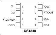
Pin Configuration Instructions This application note describes the general hardware configuration of the Dallas I²C serial interface real-time clock (RTC) and provides basic communication software routines. These devices include I²C clocks in BCD format: DS1307, DS1337, DS1338, DS1339, and DS1340. If some modifications are made to the circuit to provide a digital clock signal (32,768 Hz, 8,192 Hz, 60 Hz, or 50 Hz) for the CLK input pin, the DS1375 can also be supported. In this example, the DS2250 microcontroller is used, and the software is a C language program.
The schematic diagram is shown in Figure 1, which shows the DS1340 connection. For other types of RTC, the circuit may need to be modified. For example: DS1337, the backup battery input is replaced with an interrupt output. For low voltage RTC, it is necessary to replace the DS2250 / DS5000 with an appropriate low voltage microcontroller. Figure 2 shows the software list. #Definition description is used to indicate conditional compiled code for a specific device. This routine is used for DS1307. Before compiling the code, the #define description for DS1307 should be replaced with the correct device.
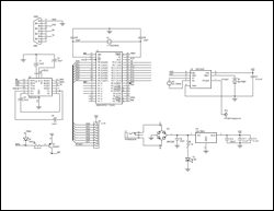
Enlarged figure 1. DS1340 and microcontroller circuit diagram
Figure 2. Software list / ******************************************** ************************ / / * DEMO1307.c * / / * program example for DS1307, DS1337 / 38/39/40 * / / * ************************************************** ***************** / #include / * Prototypes for I / O funcTIons * / #include / * Register declaraTIons for DS5000 * / / ***************************** Defines *********** ****************** / #define ACK 0 #define NACK 1 #define ADDRTC 0xd0 / * I²C slave address * / #define DS1307 / * compile direcTIve, modify as required * / / ************************* bit definiTIons ********************* **** / sbit scl = P0 ^ 0; / * I²C pin definitions * / sbit sda = P0 ^ 1; sbit sqw = P3 ^ 2; / * pin function depends upon device * / / * General Notes: Define one device to compile options for that device. * / / * Will not compile correctly if no device is defined. Not all options * / / * for each device are supported. There is no error checking for data * / / * entry. Defines may not remove all code that is not relevant to the * / / * device. This example was written for an 8051-type micro, the DS2250 / * / / * DS5000. The program must be modified to work properly on typical * / / * 8051 variants (ie assign I²C bus to unused port pins). This * / / * program is for example only and is not supported by Dallas M axim * / void I²C_start (); void I²C_stop (); void I²C_write (unsigned char d); uchar I²C_read (uchar); void readbyte (); void writebyte (); void initialize (); void disp_clk_regs (uchar); void burstramwrite (uchar); void burstramread (); void alrm_int (); void alrm_read (); void tc_setup (); / * global variables * / uchar sec, min, hr, dy, dt, mn, yr; void I²C_start () / * ----------------------------------------------- * / {sda = 1; scl = 1; / * Initiate start condition * / sda = 0;} void I²C_stop () / * ----------------------- ------------------------ * / {sda = 0; sda = 0; sda = 0; sda = 0; / * Initiate stop condition * / scl = 1; scl = 1; sda = 1;} void I²C_write (uchar d) / * ----------------------------- * / {uchar i; scl = 0; for (i = 1; i <= 8; i ++) {sda = (d >> 7); scl = 1; d = d << 1; / * increase scl high time * / scl = 0;} sda = 1; / * Release the sda ​​line * / scl = 0; scl = 1; if (sda) printf ("Ack bit missing% 02X", (unsigned int) d); scl = 0;} uchar I²C_read (uchar b) / * -------------------- --------------- * / {uchar d, i; sda = 1; / * Let go of sda line * / scl = 0; for (i = 1; i <= 8 ; i ++) / * read the msb first * / {scl = 1; d = d << 1; d = d | (unsigned char) sda; scl = 0;} sda = b; / * Hold sda low for acknowledge * / scl = 0; scl = 1; if (b == NACK) sda = 1; / * sda = 1 if next cycle is reset * / scl = 0; sda = 1; / * Release the sda ​​line * / return d ;} void readbyte () / *-read one byte of data from the specified address-* / {uchar Add; printf ("ADDRESS:"); / * Get Address * / scanf ("% bx", & Add) ; I²C_start (); I²C_write (ADDRTC); I²C_write (Add); I²C_start (); I²C_write (ADDRTC | 1); printf ("% 2bx", I²C_read (NACK)); I²C_stop ();} void writebyte () / * -write one byte of data to the specified address-* / {uchar Add; uchar Data; printf ("Address:"); / * Get Address * / scanf ("% bx", & Add); printf ("DATA : "); scanf ("% bx ", & Data); / * and data * / I²C_start (); I²C_write (ADDRTC); I²C_write (Add); I²C_write (Data); I²C_stop ();} void initialize () / * -initialize the time a nd date using entries from stdin-* / / * Note: NO error checking is done on the user entries! * / {uchar yr, mn, dt, dy, hr, min, sec, day; I²C_start (); / * The following Enables the Oscillator * / I²C_write (ADDRTC); / * address the part to write * / I²C_write (0x00); / * position the address pointer to 0 * / I²C_write (0x00); / * write 0 to the seconds register, clear the CH bit * / I²C_stop (); printf ("Enter the year (0-99):"); scanf ("% bx", & yr); printf ("Enter the month (1-12):"); scanf ("% bx", & mn); printf ("Enter the date (1-31):"); scanf ("% bx", & dt); printf ("Enter the day (1-7):"); scanf ("% bx", & dy); printf ("Enter the hour (1-23):"); scanf ("% bx", & hr); hr = hr & 0x3f; / * force clock to 24 hour mode * / printf ("Enter the minute (0-59):"); scanf ("% bx", & min); printf ("Enter the second (0-59):"); scanf ("% bx", & sec) ; I²C_start (); I²C_write (ADDRTC); / * write slave address + write * / I²C_write (0x00); / * write register address, 1st clock register * / I²C_write (sec); I²C_write (min); I C_write (hr); I²C_write (dy); I²C_write (dt); I²C_write (mn); I²C_write (yr); #if defined DS1307 || defined DS1338 {I²C_write (0x10); / * enable sqwe, 1Hz output * /} # elif defined DS1337 || defined DS1339 {I²C_start (); I²C_write (ADDRTC); / * write slave address + write * / I²C_write (0x0e); / * write register address, control register * / I²C_write (0x20); / * enable osc , bbsqi * / I²C_write (0); / * clear OSF, alarm flags * / / * could enable trickle charger here * /} #elif defined DS1340 {I²C_write (0x10); / * enable sqwe, 1Hz output * / I²C_start () ; / * address pointer wraps at 7, so point to flag register * / I²C_write (ADDRTC); / * write slave address + write * / I²C_write (0x09); / * write register address, control register * / I²C_write (0); / * clear OSF * /} #endif I²C_stop ();} void disp_clk_regs (uchar prv_sec) / * ---------------------------- ------------- * / {uchar Sec, Min, Hrs, Dte, Mon, Day, Yr, mil, pm; printf ("Yr Mn Dt Dy Hr: Mn: Sc"); while (! RI) / * Read & Display Clock Registers * / {I²C_start (); I²C_write (ADDRTC); / * write slave address + write * / I²C_write (0x00); / * write register address, 1st clock register * / I²C_start (); I²C_write (ADDRTC | 1); / * write slave address + read * / Sec = I²C_read (ACK); / * starts w / last address stored in register pointer * / Min = I²C_read (ACK); Hrs = I²C_read (ACK); Day = I²C_read (ACK); Dte = I²C_read (ACK); Mon = I²C_read (ACK); Yr = I²C_read (NACK); I²C_stop (); if (Hrs & 0x40) mil = 0; else mil = 1; if (Sec! = Prv_sec) / * display every time seconds change * / {if (mil) {printf ("% 02bX /% 02bX /% 02bX% 2bX", Yr, Mon, Dte, Day); printf ("% 02bX:% 02bX:% 02bX", Hrs, Min, Sec);} else {if (Hrs & 0x20) pm = 'A'; else pm = 'P'; Hrs & = 0x1f; / * strip mode and am / pm bits * / printf ("% 02bx /% 02bx / % 02bx% 02bx ", Yr, (Mon & 0x1f), Dte, Day); printf ("% 02bx:% 02bx:% 02bx% cM ", Hrs, Min, Sec, pm);}} if (prv_sec == 0xfe) return; prv_sec = Sec;} RI = 0; / * Swallow keypress before exiting * /} void burstramwrite (uchar Data) / * -------- fill RAM with data -------- * / {uchar j; I²C_start (); I²C_write (ADDRTC); / * write slave address + write * / I²C_write (0x08); / * write register address, 1st RAM location * / for (j = 0; j <56; j ++) / * write until the pointer wraps around * / {I²C_write (Data);} I²C_stop ();} void burstramread () / * ---------- ------------------------------- * / {uchar j; I²C_start (); I²C_write (ADDRTC); / * write slave address + write * / I²C_write (8); / * write register address, 1st RAM location -1 * / I²C_start (); I²C_write (ADDRTC | 1); / * write slave address + read * / for (j = 0; j <56; j ++) {if (! (J% 16)) printf ("% 02bX", j); printf ("% 02bX", I²C_read (ACK));} I²C_read (NACK); I²C_stop ();} void alrm_int () / * ----- initialize alarm registers ------ * / {uchar M, Sec, Min, Hr, DyDt; printf ("1-Alarm each second 2-Alarm match = sec 3-Alarm match = sec + min "); printf (" 4-Alarm match = sec + min + hr 5-Alarm match = sec + min + hr + date "); printf (" 6-Alarm match = sec + min + hr + day Enter selection: "); M = _getkey (); / * Note-N o error checking is done on entries! * / switch (M) {case '1': M = 0xf; break; case '2': M = 0xe; break; case '3': M = 0xc; break; case ' 4 ': M = 8; break; case' 5 ': M = 0; break; case' 6 ': M = 0x40; break;} if (M & 0x40) {printf ("Enter the day (1-7) : "); scanf ("% bx ", & DyDt);} else {printf (" Enter the date (1-31): "); scanf ("% bx ", & DyDt);} printf (" Enter the hour ( 1-23): "); scanf ("% bx ", & Hr); printf (" Enter the minute (0-59): "); scanf ("% bx ", & Min); printf (" Enter the second ( 0-59): "); scanf ("% bx ", & Sec); if ((M & 1)) Sec | = 0x80; if (((M >> 1) & 1)) Min | = 0x80; if (((M >> 2) & 1)) Hr | = 0x80; if (((M >> 3) & 1)) DyDt | = 0x80; if (M & 0x40) DyDt | = 0x40; I²C_start (); I²C_write (ADDRTC); / * write slave address + write * / I²C_write (7); / * write register address * / I²C_write (Sec); I²C_write (Min); I²C_write (Hr); I²C_write (DyDt); I²C_start (); I²C_write (ADDRTC); / * write slave address + write * / I²C_write (0x0e); / * write register address * / I²C_write (5); / * enable interrupts, alarm 1 * / I²C_stop ();} void alrm_read () / * ----- read alarm registers ------ * / {uchar Sec, Min, Hr, DyDt; I²C_start (); I²C_write (ADDRTC); / * write slave address + write * / I²C_write (7); / * write register address * / I²C_start (); I²C_write (ADDRTC | 1); / * write slave address + read * / Sec = I²C_read (ACK); Min = I²C_read (ACK); Hr = I²C_read (ACK); DyDt = I²C_read (NACK); printf ("Alarm 1:% 02bx% 02bx% 02bx% 02bx", Sec, Min, Hr, DyDt);} void tc_setup () / * ---- trickle charger set up routine ---- * / {uchar M, val; #if defined DS1339 #define TC 0x10 / * address for DS1339 trickle charge register * / #else #define TC 0x08 / * address for DS1340 trickle charge register * / #endif printf ("Enable Trickle Charger (Y / N)?"); M = _getkey (); if (M == 'Y' || M == 'y') {printf (" 1-250 ohm res 2-2K res = sec 3-4K res "); M = _getkey (); / * Note-No error checking is done on entries! * / Switch (M) {case '1': val = 1; break; case '2': val = 2; break; case '3': val = 3; break;} printf ("1-no diode 2-1 diode "); M = _getkey (); / * Note-No error checking is done on entries! * / Switch (M) {case '1': val + = 4; break; case '2': val + = 8; break;} I²C_start (); I²C_write (ADDRTC); / * write slave address + write * / I²C_write (TC); / * write register address * / I²C_write (val | 0xa0); / * enable trickle charger per user input * / I²C_stop ();} else {I²C_start (); I²C_write (ADDRTC); / * write slave address + write * / I²C_write (TC); / * write register address * / I²C_write (0); / * disable trickle charger * / I²C_stop ();} I²C_start (); I²C_write (ADDRTC); / * write slave address + write * / I²C_write (TC); / * write register address * / I²C_start (); I²C_write (ADDRTC | 1); / * write slave address + read * / printf ("Trickle Charger:% 02bx", I²C_read (NACK));} main (void) / * ------------------- ---------------------------------- * / {uchar M, M1; sqw = 1; / * set up for read, weak pull-up * / while (1) {#if defined DS1307 printf ("DEMO1307 build% s", __DATE__); #elif defined DS1337 printf ("DEMO1 337 build% s ", __DATE__); #elif defined DS1338 printf (" DEMO1338 build% s ", __DATE__); #elif defined DS1339 printf (" DEMO1339 build% s ", __DATE__); #elif defined DS1340 printf (" DEMO1340 build % s ", __DATE__); #endif printf (" CI Init RTC CR Read Clock "); printf (" BR Byte Read BW Write Byte "); #if defined DS1337 || defined DS1339 / * only print if part has alarms * / printf ("AI Alarm 1 Int AR Alarm Read"); #endif #if defined DS1340 || defined DS1339 / * parts that have trickle charger * / printf ("Tc Trickle charger"); #endif #if defined DS1307 || defined DS1338 / * only print if part has RAM * / printf ("RR RAM Read RW RAM Write"); #endif printf ("Enter Menu Selection:"); M = _getkey (); switch (M) {case 'A ': case' a ': printf ("Init or Read:"); M1 = _getkey (); switch (M1) {case' I ': case' i ': alrm_int (); break; case' R ': case 'r': alrm_read (); break;} break; case 'B': case 'b': printf ("Read or Write:"); M1 = _getkey (); switch (M1) {case 'R': case 'r': readbyte (); break; case 'W': case 'w': writebyte (); break;} break; case 'C': case 'c': printf ("Enter Clock Routine to run: C"); M1 = _getkey (); switch (M1) {case 'I ': case' i ': initialize (); break; case' R ': case' r ': disp_clk_regs (0x99); break;} break; case' R ': case' r ': printf ("Enter Ram Routine to run: R "); M1 = _getkey (); switch (M1) {case 'R': case 'r': burstramread (); break; case 'W': case 'w': printf (" Enter the data to write: "); scanf ("% bx ", & M1); burstramwrite (M1); break;} break; case 'T': case 't': tc_setup (); break;}}}

Pin Configuration Instructions This application note describes the general hardware configuration of the Dallas I²C serial interface real-time clock (RTC) and provides basic communication software routines. These devices include I²C clocks in BCD format: DS1307, DS1337, DS1338, DS1339, and DS1340. If some modifications are made to the circuit to provide a digital clock signal (32,768 Hz, 8,192 Hz, 60 Hz, or 50 Hz) for the CLK input pin, the DS1375 can also be supported. In this example, the DS2250 microcontroller is used, and the software is a C language program.
The schematic diagram is shown in Figure 1, which shows the DS1340 connection. For other types of RTC, the circuit may need to be modified. For example: DS1337, the backup battery input is replaced with an interrupt output. For low voltage RTC, it is necessary to replace the DS2250 / DS5000 with an appropriate low voltage microcontroller. Figure 2 shows the software list. #Definition description is used to indicate conditional compiled code for a specific device. This routine is used for DS1307. Before compiling the code, the #define description for DS1307 should be replaced with the correct device.

Enlarged figure 1. DS1340 and microcontroller circuit diagram
Figure 2. Software list / ******************************************** ************************ / / * DEMO1307.c * / / * program example for DS1307, DS1337 / 38/39/40 * / / * ************************************************** ***************** / #include
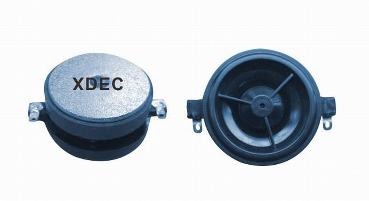
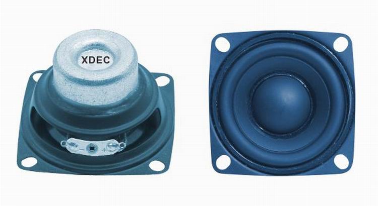
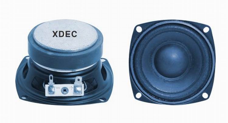
According to the working frequency response ranges, speakers can be classified into tweeters, mid ranges, woofers and full ranges.
FAQ
Q1. What is the MOQ?
XDEC: 2000pcs for one model.
Q2. What is the delivery lead time?
XDEC: 15 days for normal orders, 10 days for urgent orders.
Q3. What are the payment methods?
XDEC: T/T, PayPal, Western Union, Money Gram.
Q4. Can you offer samples for testing?
XDEC: Yes, we offer free samples.
Q5. How soon can you send samples?
XDEC: We can send samples in 3-5 days.
Speakers By Frequency,High Bass Speakers,Small Loudspeakers,High Frequency Speaker
Shenzhen Xuanda Electronics Co., Ltd. , https://www.xdecspeaker.com