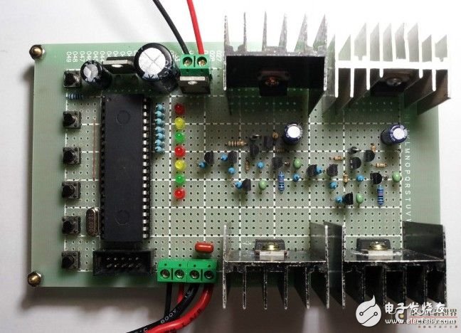
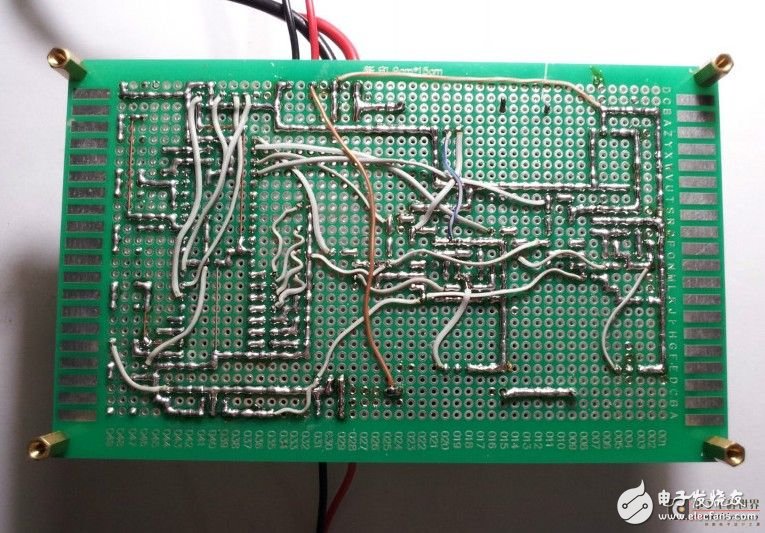
I have recently wanted to use 51 single-chip microcomputer to design and manufacture a "high-power DC brush motor PWM speed controller". Because I am busy at work, I have no time. Therefore, this stuff took me a long time. Every night, I got off work, got home and got it, and I got to rest until 11 or 2 o'clock. During the period, I also spent a lot of money and failed N times. Finally, the hard work pays off, I finally succeeded, haha~~.
Since this is a high-power DC brush motor PWM speed controller, it cannot be driven by a transistor and must be driven by a MOS tube. The MOS tube is not only highly powerful but also highly efficient. In order to improve the stability, reliability and wide application range of the system, the system is powered by dual power supplies. The control circuit is a set of power supplies with voltages of 5V and 15V, respectively. The power output is part of a set of power supplies to accommodate motors of different voltages. As for the power, it can be decided by parallel MOS tube according to the actual situation, but at the same time, the relevant parameters of the lower drive circuit must be modified, otherwise it is very likely to fry the MOS tube! In addition, I have also considered the connection between the PWM pulse output terminal and the drive circuit of the MCU through optocoupler to achieve photoelectric isolation and improve the stability of the system. But later worried about the frequency response rate of the optocoupler, it may bring signal attenuation or wrong signal to the drive circuit, which will reduce the efficiency of the system or damage the MOS tube. Maybe I care more about it. Oh, but I see a lot of information on the Internet are used for optical isolation.
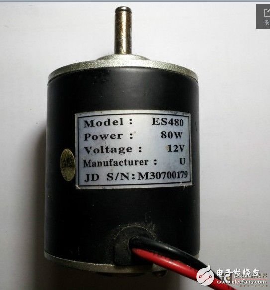
At present, this version of the speed controller, a total of 4 PWM pulse output, respectively, to: the upper and lower MOS tube drive circuit forward signal. The upper and lower MOS tube drive circuits invert the signal. In the standby state, a red LED flashes, and various status indications of the motor operation can be operated in three speeds of low speed, medium speed and high speed. Brake and reversing functions are also available. This can currently reach at least 100W without a problem. I am using a 12V 80W DC brush motor. The voltage at low speed operation is: 3.7V, at medium speed: 6.5V, at high speed: 10.5V. At present, this Dongdong only realizes the most basic control functions. There are no other functions, such as motor over-current protection, under-voltage protection (when using battery as power supply, you can use this function to protect the battery from over-discharge). These functions will be slowly studied in the future and realized. Ha ha. Not much to say, look at the photos. The source code of the program is downloaded from here: http:// I hope everyone will advise you.


Specialized Slip Ring,Slip Ring Rotary Joint,Slip Ring Induction Motor Rotor,Induction Motor Slip Ring
Dongguan Oubaibo Technology Co., Ltd. , https://www.sliprobs.com