Summary
Due to the high definition and real-time transmission advantages of SDI, it was first used in the field of professional video broadcasting. In recent years, it has been adopted more and more in the security field. However, due to the high data transmission rate of SDI and the large amount of stored data, some security practitioners who have adopted the IP network HD monitoring solution still have certain difficulties in design and application. To help readers more fully understand and design SDI, this article describes how to choose the appropriate SDI signal chain device, how to design a high-performance SDI signal chain, introduces the basic working principle of equalizer, cable driver, retimer, PCB cloth Recommendations for board and power supply design and TI's specific solutions in the SDI field.
1. Introduction to SDI
SDI, serial digital interface, is a standard for transmitting uncompressed digital video signals such as standard definition, high definition, and 3G high definition. The most popular SDI video formats are shown in Table 1. Due to the high-definition characteristics of SDI, the delay is small, and the advantages of the already-used analog video cable can be reused, and it is gradually being widely adopted in the fields of security and monitoring. Currently, SDI related devices on the market are mainly SDI extenders, splitters, matrices, multi-screen splitters, codecs, SDI optical transceivers, DVRs, and the like.
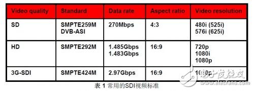
Compared to traditional IP surveillance networks, the advantages of SDI are very obvious:
SDI has an unparalleled advantage in image clarity
HD doesn't just mean high resolution, it also has excellent performance in ultra-wide dynamics, white balance, signal-to-noise ratio, brightness, contrast, sharpness, and more. Due to the compression and compression of the IP network surveillance video, the above image quality and image details are far less than the uncompressed SDI.
SDI transmission is strong in real time
The transmission of the SDI signal does not pass through the compression link, and there is no processing delay; it does not pass through the IP network and is not affected by the network delay.
Upgrade from analog monitoring system to SDI to reuse existing wiring systems
SDI also uses coaxial 75 ohm cable and BNC interface, which can be easily and quickly upgraded from traditional analog monitoring system to SDI without having to re-arrange the network like IP network. This feature has the upgrade of analog monitoring system. A huge advantage, because the construction of the IP network is not allowed for many buildings.
On the other hand, SDI also has shortcomings, such as higher cost at present, large data storage, and difficulty in long-distance transmission design. However, as SDI is gradually adopted by the market, the above shortcomings will gradually weaken.
2. Working principle of SDI device and TI related product introduction
Figure 1 is a block diagram of a typical SDI input, output, and processing application. TI can provide a full set of SDI transmission schemes: equalizer, cable driver, retimer, crossbar matrix, video clock, display driver, Storage drive and power supply.
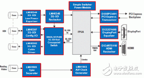
Figure 1 Typical SDI application
2.1 equalizer
The high-frequency components of the signal are attenuated more frequently than the low-frequency components of the signal after being routed through the PCB trace or cable. This phenomenon is known as the skin effect, which destroys the signal integrity of high-speed signals and causes their eye diagrams to be turned off. And increase signal jitter. In order to compensate for the skin effect, an equalizer, a pre-emphasis, and a de-emphasis are invented to compensate for the unevenness of the transmission line frequency response. Figure 2 is a frequency response diagram of a transmission line and an equalizer. The transmission line model attenuates more at high frequencies and the equalizer has higher gain at high frequencies, setting the high frequency gain of the equalizer to an appropriate value. The transmission line and the equalizer are connected in series to form a substantially flat frequency response over the full frequency band.
Usually pre-emphasis and de-emphasis are used at the transmitting end of high-speed digital signal transmission, and equalizer is used at the receiving end, but in the SDI link, only the equalizer is used at the receiving end, and generally it is an adaptive equalizer, but not at the transmitting end. Pre-emphasis or de-emphasis, because SDI devices may be connected by any user-defined coaxial cable of any length, any fixed equalization or pre/de-emphasis value can not flexibly meet various cable lengths, and the industry has not yet Adaptive pre-emphasis and de-emphasis. In addition, SDI devices must be plug-and-play, allowing customers to manually set the appropriate equalization values ​​at the application site for optimal cable transfer characteristics. Therefore, only the adaptive equalizer is an ideal solution. The adaptive equalizer can automatically detect the signal quality and correspondingly set the optimal equalization value to get the best transmission channel frequency response.
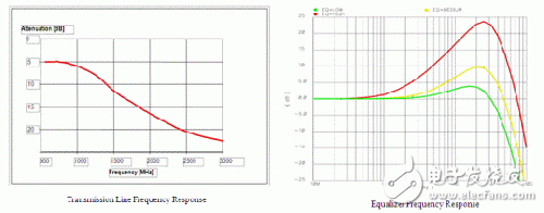
Figure 2 Frequency response of the transmission line and equalizer
Figure 3 shows the effect of the equalizer. It can be seen that the eye diagram and jitter performance of the high-speed SDI signal are significantly improved by the equalizer after a cable or PCB trace.
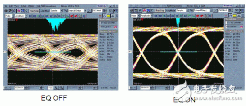
Figure 3 The effect of the equalizer
TI offers a full range of equalizers supporting SD, HD, and 3G SDI, as shown in Table 2.
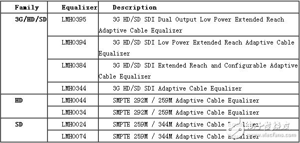
Table 2 Equalizer
The LMH0394 is an extremely high performance equalizer. Its competitive analysis is shown in Figure 4. The transmission distance is very long and the power consumption is very low.
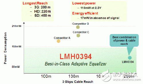
Figure 4 Equalizer LMH0394 Competitive Analysis
2.2 Retimer
The SDI retimer is used to automatically detect the type of input signal, adjust its own PLL and CDR circuit to recover and shape the low jitter clock, and then re-timed out the received SDI signal to reduce the jitter of the SDI signal. Although the equalizer can also reduce the jitter of the SDI signal, it and the retimer are two completely different devices, and the two cannot be replaced. The role of the equalizer is to improve the eye diagram and signal jitter by increasing the high frequency gain to flatten the transmission channel frequency response, while the retimer suppresses and reduces the accumulated noise through the PLL and CDR. If the SDI transmission channel is long or the other noise and interference are degraded during transmission, only the equalizer is not enough to improve the quality of the signal. In this case, a re-sequence is connected to the equalizer output to improve the SDI signal. Quality program. Figure 5 depicts the debounce effect of the retimer, showing that the eye diagram and jitter are significantly improved.
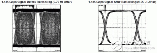
Figure 5 Retimer effect
The TI retimer product line is shown in Table 3.

Table 3 Heavy Timer Series
2.3 cable driver
SDI cable drivers are used to enhance cable drive capability, providing a standard 800mV peak-to-peak output voltage swing with no pre-emphasis and de-emphasis. TI's cable driver family is shown in Table 4.

Table 4 Cable Driver
Diesel Generator,Xcmg Diesel Power Set,Trailer Type Generators,Marine Diesel Generator Set
XCMG E-Commerce Inc. , https://www.xggenerators.com