The UIO here is Userspace I/O. In this article, UIO refers to the UIO device and the UIO driver. It is relatively small in the world of Linux kernel, mainly some custom devices and corresponding drivers. The UIO kernel driver is responsible for exposing the interrupt and device memory to the user space, and then the UIO user state driver (ApplicaTIon) to implement the specific business and play as desired. The academic point is called highly customized and flexible design.
So how does it relate to FPGA? Yes, FPGAs are also free to play in the hardware world. This hard and soft is really right, together.
This lab project will show you how to implement multiple UIOs on the Xilinx heterogeneous multiprocessor product family Zynq UtralScale+ MPSoC ZCU102 embedded evaluation board, and complete the hardware engineering and linux BSP development with Xilinx tools. The test application completes the test.
The MPSoC integration on the ZCU102 cures the quad-core ARM Cortex-A53, dual-core Cortex-R5 and Mali-400 MP2 GPU, which is officially known as the PS (Processing System). The other part is the FPGA, PL (Programmable Logic). The PS side implements control, and the PL is used to implement application acceleration, and the two are connected through AXI. Run this little experiment, huh, huh, overkill. It’s just that I have the board on hand. The cheese can go buy a Zybo or ZedBoard development board and try it out on the board.
Experimental report Experimental materials:

The hardware design builds the Vivado project and adapts to the ZCU102 EVB. Join the PS through IP Integrator and add 5 UIO inputs on the PL side, one of which is the GPIO module (including interrupt output and device memory), and the other 4 are PIN connected to the DIP switch on the ZCU102 EVB as a interrupt input through a concat The IP is connected to the ps_pl_irq pin of the PS. Board level details please refer to [1] UG1182, chip data reference [2] UG1085
Add a PIN constraint file,
Set_property PACKAGE_PIN AN13 [get_ports pl_irq_ll]
Set_property IOSTANDARD LVCMOS33 [get_ports pl_irq_ll]
Set_property PACKAGE_PIN AM14 [get_ports pl_irq_lh]
Set_property IOSTANDARD LVCMOS33 [get_ports pl_irq_lh]
Set_property PACKAGE_PIN AP14 [get_ports pl_irq_ef]
Set_property IOSTANDARD LVCMOS33 [get_ports pl_irq_ef]
Set_property PACKAGE_PIN AN14 [get_ports pl_irq_er]
Set_property IOSTANDARD LVCMOS33 [get_ports pl_irq_er]
Vivado's graphical module design, rich IP library, and smart connectivity. A little bit of digital circuit design, this small design can be completed very quickly. The entire design is shown below.

Software Design Here I use Xilinx's Petalinux for Linux BSP. It is based on Yocto, which joins Xilinx's Layers to implement hardware engineering import, simplifies the packaging process of complex Yocto, supports certain user-defined functions, such as QEMU simulation run, increases out-of-tree driver, and device tree modification. The application is compiled and packaged, and so on. For more information, please go to https://china.xilinx.com/products/design-tools/embedded-software/petalinux-sdk.html
Here is a brief demonstration of the specific command process.
$petalinux-create -t ​​project --template zynqMP -n zcu102-pl2ps_irq
$cd ./ zcu102-pl2ps_irq
$petalinux-config --get-hw-descripTIon
$petalinux-config -c kernel
Enable UIO_PDRV_GENIRQ driver
CONFIG_UIO=y
# CONFIG_UIO_CIF is not set
CONFIG_UIO_PDRV_GENIRQ=y
$petalinux-build -c device-tree
The dtsi file on the PL side is generated with ./components/plnx_workspace/device-tree-generaTIon/pl.dtsi
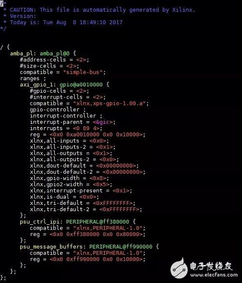
There is only GPIO UIO here. Since PIN UIO is not IP, the related information cannot be automatically generated by the tool. So make the following changes:
1. Modify the GPIO UIO device endpoint 1) Change the interrupt number to 93
2) Change compaTIble to "generic-uio" //We will use the UIO_PDRV_GENIRQ driver that comes with Linux.
2. Add DIP UIO endpoint 1) Change compatible to "generic-uio"
2) Set the interrupt value 89 to 93 in order
3) Set the attribute value according to the interrupt trigger type of each DIP PIN
* The interrupt number in the DTS and the hardware interrupt number have an offset of 32.
Petalinux provides a custom DTS file./project-spec/meta-user/recipes-bsp/device-tree/files/system-user.dtsi to define the above changes to system-user.dtsi.
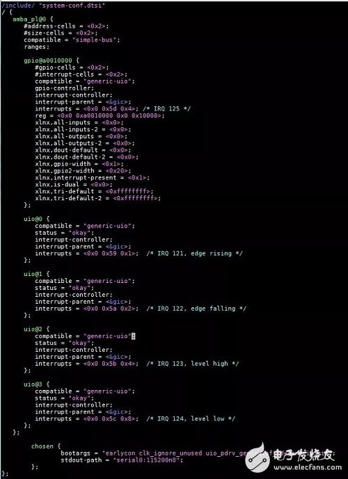
There are two ways to adapt the UIO endpoint and the UIO_PDRV_GENIRQ driver
1. bootargs use "uio_pdrv_genirq.of_id=generic-uio", which can be defined by DTS.
2. insmod uio_pdrv_genirq.ko of_id=generic-uio when install the driver
After the modification, compile the Image.
$petalinu-build
$cd ./images/linux
$petalinux-package --boot --fsbl zynqmp_fsbl.elf --fpga --atf --pmufw --u-boot --force
Copy the generated BOOT.bin (bootloader) and image.ub (FIT uImage) to the SD card for booting. \
Test the introduction of the uio_pdrv_genirq driver referenced here.
Https://01.org/linuxgraphics/gfx-docs/drm/driver-api/uio-howto.html
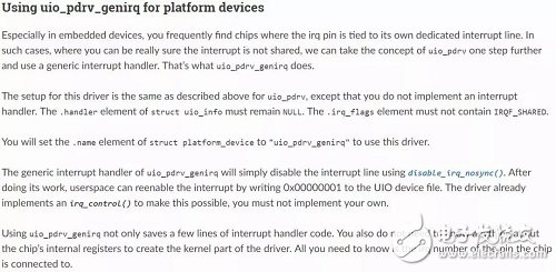
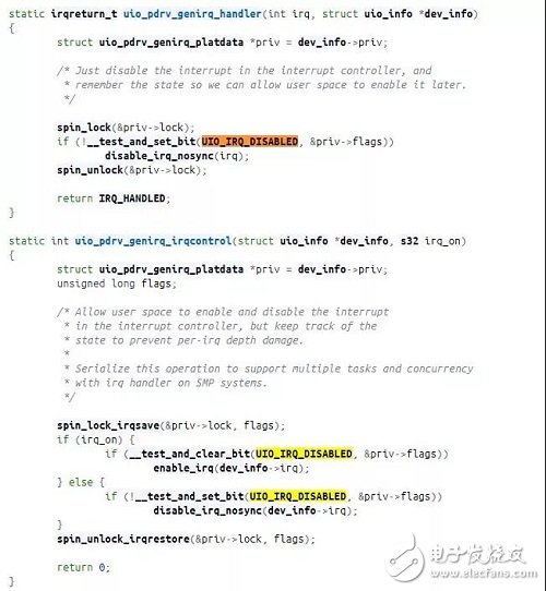
Combined with the driver code ./drviver/uio/uio_pdrv_genirq.c), each UIO device will have a corresponding device node for /dev/uioX. User mode driver reads will block until a UIO hardware interrupt occurs. UIO's interrupt handler uio_pdrv_denirq_handler() closes the hardware interrupt. The user mode driver needs to trigger uio_pdrv_genirq_irqcontrol() through the write function to complete the interrupt enable and disable. code show as below,
Boot the kernel and load the uio_pdrv_genirq driver
Check /proc/interrupts
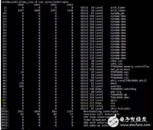
Careful you must have found a pit, missing 2 UIO interrupts (IRQ122 and IRQ124), the original hardware does not support Edge falling and Level Low trigger mode. The kernel log is as follows.

Test DIP UIO method one by dialing 2 DIPs, observed
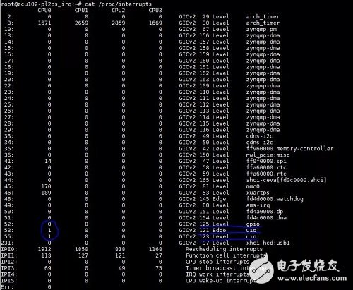
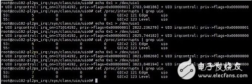
Two DIP interrupts have occurred, but it is always 1 regardless of how the DIP switch is toggled. In the previous paragraph, this interrupt will be turned off in the driver's interrupt handler, which needs to be opened by the application calling write(). There is an easy way here, use the versatile echo command "echo 0x1 > /dev/uioX", and with DIP can trigger multiple interrupts.
Test DIP UIO Method 2 The previous method is relatively low, here is a slightly advanced enjoyment. Write a simple user mode driver, on the code.
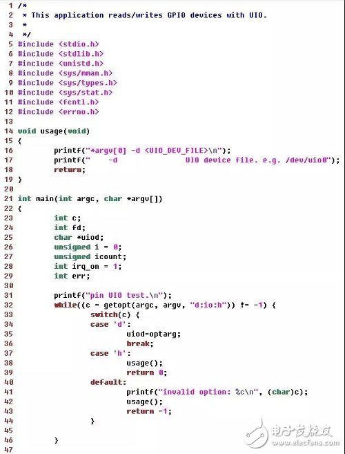
Compile the bin file with the cross-compiler tool provided by petalinux and copy it to the boot SD card.
Run the test program and test with the DIP switch. (In order to better reflect the test operation, the irqcontrol call is added to the UIO kernel driver)
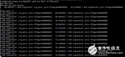
Test GPIO UIO
The UIO driver enumerates the device memory (register) space, and the user mode driver uses the mmap export for read and write control. See the AXI_GPIO IP document pg144-axi-gpio.pdf, whose registers are as follows.
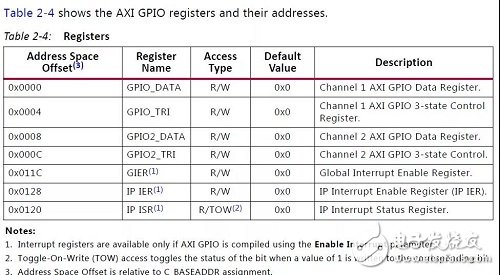
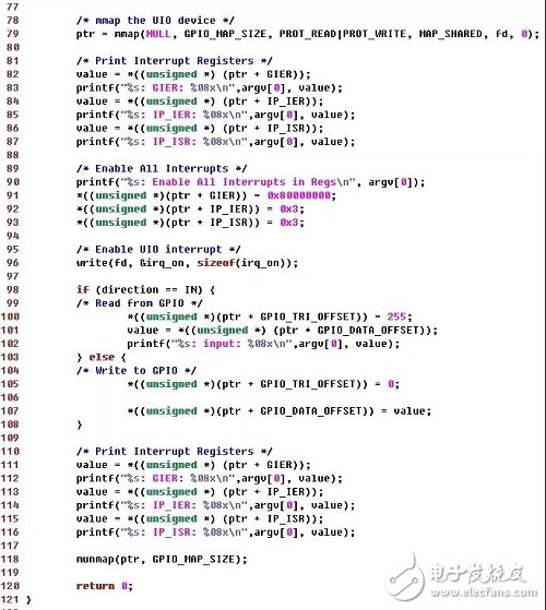
The test application will enable interrupts by setting GIER and IP_IER. On the code.
Testing process
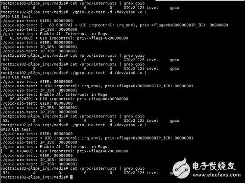
Perhaps you feel that such a map code is not kind and can not be used to copy and paste Dafa, but I do not know that I am WORD, did not try to make a good layout. Don't worry, here is GIT, https://gitenterprise.xilinx.com/AlexHe/UIO_Linux_Demo
Hardware resource files and Image, test code can not be less, all presented. Is it sour?
Experimental results
UIO's highly customizable device combined with Xilinx's MPSoC enables very flexible applications. Xilinx provides a complete set of tools that give users an efficient development experience. Although this example is simple, the concept of All Programmable that Xilinx advocates and the actual FPGA acceleration application are indeed based on these hardware and software collaboration technologies. Forget it!
male-female connector,luminarie disconnect,Wire Terminal Block Led Connectors,Electric Wire Plastic Connector
Guangdong Ojun Technology Co., Ltd. , https://www.ojunconnector.com