With the widespread use of color displays in the portable market (such as mobile phones, PDAs, and ultra-compact PCs), for a monochrome LCD lighting, a white backlight or side light is required. Compared with commonly used cold cathode fluorescent lighting (CCFL) backlights, white LEDs seem to be a good choice for backlight applications because they consume less power and require less space. The typical forward voltage of white LED is between 3V and 5V. Since the best choice for powering white LEDs is to choose a constant current power supply, and the input voltage range of the lithium ion battery is lower than or equal to the LED forward voltage, a new power supply solution is needed.
The main power requirements include high efficiency, small solution size, and the possibility to adjust the LED brightness. For portable systems with wireless capabilities, acceptable EMI performance has become another focus of our attention. When the efficiency is the standard we care about most when choosing a power supply, the boost converter is an attractive solution, and the other common solution is to use a charge pump converter. In this article, we separately discussed two solutions for driving white LEDs and discussed their relationship with the main power requirements. Another very important design consideration is the control method of adjusting the brightness of the LED. The brightness not only affects the efficiency of the entire converter, but also may cause the chromaticity conversion of the white LED. The following will introduce a simple solution that uses a PWM signal to control its brightness. Compared with other standard solutions, another advantage of this solution is its higher efficiency.
task
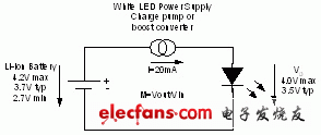
Once the power supply is selected for white LEDs, the main requirements for a portable system are efficiency, overall solution size, solution cost, and the last but very important electromagnetic interference (EMI) performance. Depending on the portable system, the emphasis on these requirements varies. Efficiency is usually the most important or sub-important consideration in key design parameters, so this factor should be carefully considered when selecting a power supply. Figure 1 shows the basic circuit of a white LED power supply.

Figure 1 An excellent efficiency requires a variable conversion gain M
The Li-Ion battery has a voltage range between 2.7V and 4.2V. The main task of this power supply is to provide a constant current and a typical 3.5V forward voltage for the white LED.
Boost converters can achieve higher efficiency compared to charge pump solutions
In general, there are two power supply topologies for driving white LEDs: a charge pump or switched capacitor solution and a boost converter. Both solutions can provide higher output and input voltages. The main difference between the two is that the conversion gain M = Vout / Vin, which will directly affect the efficiency; and generally speaking, the conversion gain of the charge pump solution is fixed. A simple charge pump solution with a fixed conversion gain of 2 usually produces a voltage much higher than the LED forward voltage, as shown in equation (1). It will bring an efficiency of only 47%, as shown in equation (2).

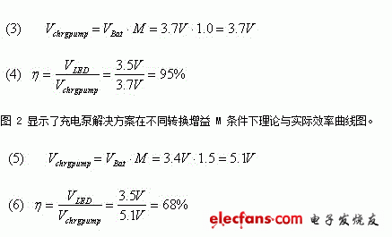
In the formula, Vchrgpump is the voltage generated inside the charge pump IC, and VBat is the typical battery voltage of a lithium-ion battery. The charge pump needs to provide a constant current and an output voltage equivalent to the typical forward voltage of 3.5V of the LED. Generally, a charge pump with a fixed conversion gain of 2 generates a higher voltage internally (1), which causes an internal voltage drop and reduces the overall system efficiency (2). More advanced charge pump solutions overcome this shortcoming by switching between 1.5 and 1 conversion gain. In this way, when the battery voltage is slightly higher than the LED voltage, it can be operated between 90% to 95% efficiency level, thus allowing the use of a conversion gain of 1 gain. Equation (3) and equation (4) show this performance improvement:
When the battery voltage is further reduced, the charge pump needs to be converted to a gain of 1.5, thereby reducing the efficiency to 60% to 70%, as shown in examples (5) and (6).

Figure 2 Efficiency changes of the charge pump solution
A true double voltage charge pump with a conversion gain of 2 has very low efficiency (as low as 40%) and is not very attractive to portable devices; while a charge pump with a combined conversion gain (gains of 1.0 and 1.5) Shows a better effect. The next problem of such a charge pump is the conversion point from gain M = 1.0 to M = 1.5, because the efficiency will drop to 60% after gain conversion occurs. When the efficiency of the battery decreases (switches) where it can operate normally for most of the time, the overall efficiency decreases. Therefore, high efficiency can be achieved when switching occurs at a low battery voltage close to 3.5V. However, this switching point depends on the LED forward voltage, LED current, charge pump I2R losses, and the voltage drop required by the current sensing circuit. These parameters will move the switching point to a higher battery voltage. Therefore, such a charge pump must be carefully evaluated in a specific system to achieve high efficiency values.
The calculated efficiency value shows the best theoretical value of the charge pump solution. In real life, depending on the current control method, more losses will occur, which has a very large impact on efficiency. In addition to I2R losses, the switching and static losses in this device will further reduce the efficiency of the charge pump solution.
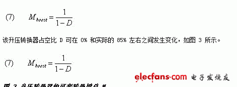
These shortcomings can be overcome by using an inductive boost converter, which has a variable conversion gain M, as shown in equation (7) and Figure 3.

Figure 3 Variable conversion gain M of the boost converter
Power Lan Transformers For Automotive Product,Ferrite Core Pluse Transformer,High Power Pulse Transformer,Pulse Transformer Vs Power Transformer
IHUA INDUSTRIES CO.,LTD. , https://www.ihua-magnetics.com