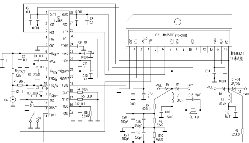
The 125W Class D subwoofer power amplifier circuit designed with the newly introduced LM4651 and LM4652 of National Semiconductor Corporation is shown in the figure. The output power of this amplifier under total harmonic distortion THD = 1% is 125W, the load impedance RL = 4Ω, the maximum level of the input signal Vin (rms) is 3V, the input signal bandwidth is 10 ~ 150Hz, the ambient temperature is 50 ℃, The power supply voltage is ± 20V.
The LM4651 in a 28-pin DIP package is a PWM control / driver IC with built-in oscillator, PWM comparator, error amplifier, feedback amplifier, level shifting and high-end driver, low-side driver, and protection circuits for undervoltage, overheat, short circuit, and overmodulation . LM4652 is a half-bridge power MOSFET IC with 15 pins (6, 8, 9, {11} and {12} pins are not connected), TO-220 package, 4 MOSFET breakdown voltage V (BR) DSS = 50V, Drain current ID = 10A, on-state resistance RDS (ON) = 200mΩ (typical value), turn-on voltage VGS (th) = 0.85V (typical value).
In LM4651, the oscillator frequency fosc = 1 × 10⁹ / (4000 + Rosc), where Rosc = R6 = 3.9kΩ, so fosc = 125kHz. The input audio signal is input to the error amplifier with a gain of 7? 5V / V (that is, 17? 5dB) through C1, R1, and 10 feet. The output of the half-bridge switch on pin IC27 and pin {15} is filtered by the RC filter and fed back to pin {14} and pin {19} of IC1 through the internal feedback measurement amplifier, and then pin 10 is output from pin 9 to provide an error amplifier. A single-ended feedback signal. The audio input signal is compared with the triangular wave generated by the oscillator, and a square wave pulse with a duty cycle proportional to the level of the input audio signal is generated at the output of the PWM comparator to drive the power MOSFET in IC2. The switch output of IC27 pin and {15} pin is low-pass filtered by L1, C16 and L2, C17 to drive the speaker to work.
Resistor R4 on IC1 {18} pin is used as short-circuit current limit. When R4 = 100kΩ, the short-circuit current level is not less than 10A; the resistor R5 on the {17} pin is used to set the dead time; the capacitor C9 on the {24} pin is used to set the start delay time (1 second) When the {13} pin (STOBY) is placed in logic "1" or 5V, it performs the standby function, stops pulse width modulation, and turns off the power switch in the LM4652, consuming only a very low current. As long as the junction temperature of IC2 reaches 150 ° C, the output of its 4-pin is fed back to the {12} pin of IC1 to perform the thermal shutdown function.

Follow WeChat

Download Audiophile APP

Follow the audiophile class
related suggestion
Avago Introduces New High Linear Power Amplifier Module Product Avago Technologies ...
The circuit is shown in Figure 1. The chip IC uses the LM1875 of the American NS company, which has a soft tone and low distortion (0.015% ...

The word "Monster" has both positive meaning and ...
When the output power of the digital power amplifier is greater than 50W, it is impossible to use only ...
If an "audiophile" is a group of people who are never satisfied with the sound and "loved the new and the old" with the audio equipment. Then just rely on these so-called "fever spirits" ...
First, the circuit principle and characteristics 1. Power amplifier part (see Figure 1)
There is a well-known saying in the Hi-Fi world that is "briefness first." This means that if ...
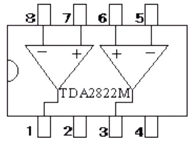
Simple and practical TDA2822M integrated power
TDA2030 is ...

STK465 thick film ...

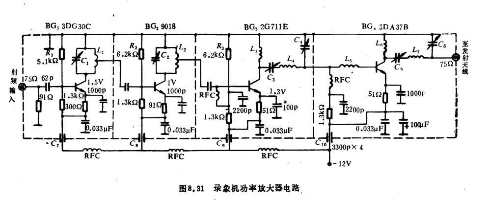
This RF power amplifier can output 2-3 channel signals, covering an area of ​​about one square kilometer, is ...
![[Photo] 120db frequency sweeping siren circuit](http://i.bosscdn.com/blog/20/06/41/6175853271.gif)
![[Photo] 15w RF power amplifier](http://i.bosscdn.com/blog/20/06/41/521040781.gif)
![[Photo] Broadband high frequency power amplifier](http://i.bosscdn.com/blog/20/06/41/520536801.jpg)
Low frequency power amplifier
![[Photo] TDA2030 audio power amplifier](http://i.bosscdn.com/blog/20/06/41/5131012891.gif)
Looking at the Hi-Fi amplifiers currently on the market, the output power is 100W ...
![[Photo] Transistor 15W Class A Power Amplifier](http://i.bosscdn.com/blog/20/06/41/513102891.gif)
![[Photo] Mark Levinson No. 30 ...](http://i.bosscdn.com/blog/20/06/41/513544752.jpg)
EL34 (6CA7) was first launched by Philips in 1956 ...
![[Photo] 45W transistor tube hybrid power amplifier](http://i.bosscdn.com/blog/20/06/41/513531952.jpg)
This article cleverly combines the electronic tube EL34 and the transistor (op amp), ...
![[Photo] 32W hybrid audio power amplifier](http://i.bosscdn.com/blog/20/06/41/513526493.jpg)
The pre-amplifier adopts a European-made TESLA brand low noise high cheek double transistor ...
![[Photo] Gallstone hybrid power amplifier using switching power supply](http://i.bosscdn.com/blog/20/06/41/513524776.gif)
"Simple" means the circuit of the amplifier is simple, making it easier, as long as the picture ...
![[Photo] Simple fool power amplifier](http://i.bosscdn.com/blog/20/06/41/513432946.jpg)
1. Description: & nb ...
![[Photo] LM386 low voltage audio power amplifier ...](http://i.bosscdn.com/blog/20/06/41/513417261.gif)
The Class A transistor power amplifier has a warm and sweet tone, which makes people tempted. But the temperature rise of Class A amplifier ...
![[Photo] Class A power amplifier using SAP15N / P audio pair tube ...](http://i.bosscdn.com/blog/20/06/41/513346769.gif)
The circuit is shown in Figure 5, ...
![[Photo] Using TDA7294 and 2SA1216 / 2S ...](http://i.bosscdn.com/blog/20/06/41/4233420295.gif)