The current mainstream train communication network (TCN) consists of a twisted-line train bus (WTB) and a multi-function vehicle bus (MVB). Today we will learn about the serial data communication bus WTB designed for interconnecting vehicles as a train compartment. How the bus protocol of communication controls the normal operation of the network communication of the entire train.
1. Overview of WTB
WTB is a twisted-line train bus. It is based on the data communication experience of German DINV3322 and Italian CD450 high-speed trains. It is often used for reconnected vehicles that are connected and disconnected. WTB uses a dedicated shielded twisted pair cable. The wiring is arranged with redundancy and there is one cable on each side of each vehicle. To accommodate trains that frequently change their composition, the WTB is designed to interconnect vehicles by hand-over jumper cables or automatic connectors.

Since WTB operates with twisted-pair shielded wires, its transmission rate is 1 Mbit/s and the specified type of cable is used. WTB meets the requirements of UIC556, which defines the communication requirements for UIC trains consisting of up to 22 buses, up to 860m in length, longer distances and more nodes (up to 62). WTB media is made up of cable nodes on different vehicles.

Figure 2 train
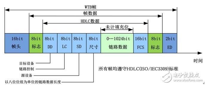
2, WTB data frame structure
The WTB data frame format includes the main frame data of the bus master and the slave frame data of the slave device, and the main frame and the slave frame form a message, and the format of the main frame and the slave frame are unified, as shown in FIG. 3 below. All frame data have the same coding structure and conform to the structure of the HDLC signal in the ISO/IEC 3309 standard. The 6-bit frame header and the 2-bit high-level termination delimiter are not part of the frame data, but they are part of the WTB frame.

Figure 3 WTB topology
Header (SH): The frame header is generated by the Manchester encoder and is removed by the Manchester decoder. The length is 16~32 bits. The default value is 16 bits.
Frame Data Flag (DS/DE): Frame data uses two 8-bit flag delimiters to determine the start and end of a frame.
Target device DD: Indicates the 8-bit node address of the received data frame, ranging from 1 to 63, which is allocated during the initial run. Address 255 is the broadcast address that all nodes answer.
Link Control LC: Used to distinguish between request frame (primary frame) and response frame (slave frame). If the highest bit of the LC is "1", the data frame is the request frame (main frame). If the highest bit of the LC is "0", the data frame is the response frame (slave frame).
Device Source SD: The physical address of the sending frame node.
Link data length: The effective link data length sent by the data frame, ranging from 0 to 128 bytes.
End delimiter ED: 2 bits high.
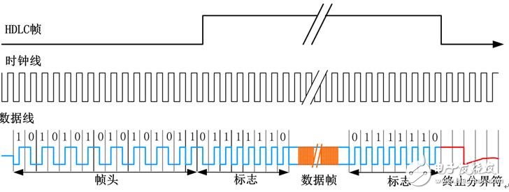
The specific data coding structure is shown in Figure 4 below:

Figure 4 WTB data sequence
The frame header follows the Manchester coding principle during encoding (from high to low, 0, low to high 1). A frame signal begins with a frame header starting with a starting "S" of level "1" followed by a number of ("0", "1") bit pairs, the last bit being "1". The frame start and end identification flags are 01111110, and the end of the frame is terminated by a 2-bit high-level termination delimiter, which returns to the idle level, as shown by the red flag in Figure 4.
High Voltage Lan Transformer,High Voltage Pwoer Pulse Transformer,Cmc Coilfor Automotive Product,High Voltage Pulse Transformer
IHUA INDUSTRIES CO.,LTD. , https://www.ihua-sensor.com