Multi-touch technology With the popularity of the iPhone, people are familiar with and concerned, the traditional resistive touch technology is gradually replaced by LLP technology and capacitive touch technology. Although Tutuo Technology focuses on large-size touch technology and LLP technology, it is also involved in capacitive touch technology. This article focuses on a brief analysis of several categories of capacitive touch technology.
This article refers to the address: http://
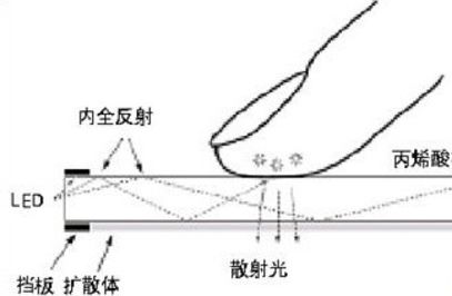
Multi-touch diagram
The technical operation of multi-touch is inevitable through a carrier, which is the screen we are facing today. Taking the well-known products of mobile phones as an example, mobile phones with touch screen design in the mobile phone field have already occupied most of them, that is, most of the mobile phones we use now can be operated by touch commands. Typical examples are: Nokia's 5800XM, Apple's iPhone, or Sony Ericsson's X10, but have you ever wondered why Nokia's 5800XM and Apple iPhone 4 can't stand on one level? There are many reasons for this. It must be recognized by us: that is, they are all touch screen mobile phones, and the choice of screen materials is different, leading to the final product positioning. The former uses a resistive screen for single-touch, and the latter with a capacitive screen for multi-touch, higher resolution, clearer display, and more entertainment. This is why resistive touch technology is gradually being replaced by capacitive technology.
It seems that in terms of screen selection, it is also a measure that can define whether the aircraft is at a high level. However, there are doubts that we found out that the iPhone and the Sony Ericsson X10 are both capacitive screens. Why can the former be multi-touch, and the latter can't? The Nokia 5800XM can't be multi-touch, which is the reason for its resistance screen, then X10 Why is the capacitive screen not capable of multi-touch, software or hardware? Similarly, since the iPhone 4 supports multi-touch, what are the main differences between the two? This is to talk about the major categories of capacitive touch technology.
Capacitive touch technology classification
There are two main types of capacitive screen technology: Surface Capacitive technology and Projective Capacitive technology.
Surface Capacitive technology, that is, its structure is relatively simple, using a layer of ITO glass as the main body, at least four electrodes on the periphery, providing voltage at the four corners of the glass, forming a uniform electric field on the surface of the glass, when the user touches When the operation is performed, the controller can detect the position of the touch coordinates by using the change caused by the electrostatic reaction between the human finger and the electric field. This type of architecture determines that surface capacitive technology cannot achieve multi-touch functionality because it uses a homogeneous sensing layer that aggregates all signals sensed at any location on the touch screen into one The larger the signal, the homogenous layer destroys too much information, so that multi-touch can't be sensed. In addition, the surface capacitive touch screen also has the difficulty of miniaturization, which is difficult to apply to mobile phone screens, and is mostly used in medium and large size fields. (This technology is difficult to implement in mobile applications, excluding X10, iPhone 4)
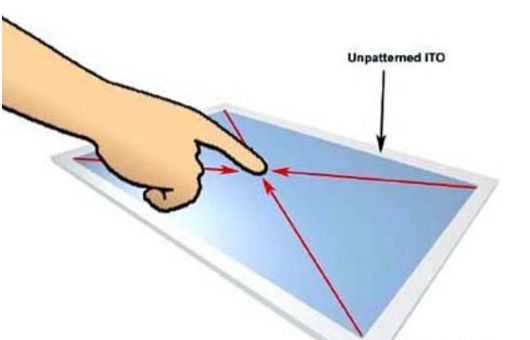
Surface capacitance application
Projective Capacitive technology, its basic technical principle is still based on capacitive sensing, but compared to the surface capacitive touch screen, the projected capacitive touch screen uses multiple layers of ITO layer to form a matrix distribution, with X-axis, Y The axis cross distribution is used as a capacitance matrix. When the finger touches the screen, the X and Y axis scans can be used to detect the change of the capacitance of the touch position, thereby calculating the position of the finger. Based on this architecture, the projected capacitor can be multi-touch operated.
Application of projected capacitance
There are two main touch technologies for projected capacitors: one is self capacitance (also called absolute capacitance), and the other is mutual capacitance (also known as transcapacitance). The self-capacitance type refers to the capacitive coupling between the touch object and the electrode, and the capacitance change of the measuring electrode determines the occurrence of the touch; the mutual capacitance type is that when the touch occurs, a capacitive coupling phenomenon occurs between the adjacent two layers of electrodes.
According to these two principles, different projected capacitive architectures can be designed, and the multi-touch functions that different architectures can achieve are different. Multi-touch can be subdivided into two types: one is Gesture interaction, which is to detect and distinguish multi-touch behaviors such as zoom, drag, rotate, etc. Axis intersecting technology; the other is to find multi-touch individual positions, which requires complex point-to-point (APA) technology.
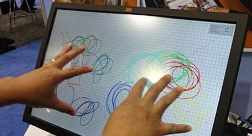
Projection capacitor practical application
Axis interleaved
The axis-interleaved (also known as Profile-based) technology is to plan the diamond shape sensing unit on the conductive layer, and each layer needs a conductive layer. Taking the 2-axis type as an example, when the touch is detected, the sensing controller scans the horizontal/vertical axes separately, and the horizontal/vertical sensing points that generate capacitive coupling will have rising peaks, and the two-axis intersection will be Correct touch point. Since each measurement is a capacitive coupling phenomenon with a single conductive layer and a touch object, it is a self-capacitance type technology.
The axis interleaved capacitive touch technology is actually the implementation technology of the touchpad touchpad. The technology is quite mature, but the biggest difference between the touchpad and the touchscreen is that the former is opaque and the latter is transparent. of. Because of the opacity, the touchpad can use metal or carbon atomic electrodes in the sensing region. The projected capacitive touch screen is transparent, so transparent ITO is required as the conductive electrode, and this layer of ITO is not like a resistive or surface capacitive type, which is a uniform conductive layer, and needs to be patterned.
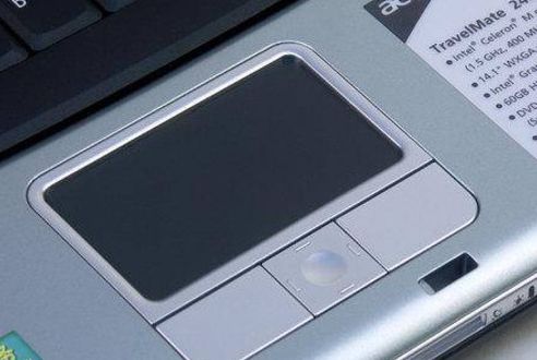
Notebook trackpad
In single-touch applications, the axis interleaving can get the exact touch position, so unlike surface capacitance, calibration correction is required. Through some algorithms, the axis interleaving can also achieve multi-touch gesture recognition, but it is difficult to locate the correct position of multi-touch. In the 2-axis scan, the two touch points will generate two peaks on the X-axis and the Y-axis, respectively, and four contacts will be generated when the intersection is made, and two of them are false touch points (Ghost point). This will cause the system to be unable to interpret correctly.
However, there are still ways to solve the multi-point positioning problem. In the 2-axis touch screen, the front/rear contacts can be distinguished by two finger touch time differences, or can be distinguished by different moving directions of the contacts. In addition, the axial position can be increased to increase the position and number of identifiable contacts. For each additional 1 axis, 1 point can be recognized (such as 2 points for 3 axes and 3 points for 4 axes); however, each additional axis is added. It is necessary to have one more conductive layer, which will increase the thickness, weight and cost of the designed touch panel, which is not the result of the portable product.
Contact positionable
The All Point addressable technology can achieve multi-touch function and can identify the exact location of the touch point. It can be said to be an ideal multi-touch solution. The iPhone uses this touch technology. . It is mainly constructed as two conductive layers, one of which is driving lines and the other is sensing lines, and the two layers are perpendicular to each other. In operation, a driving line is driven in turn, and the sensing line interleaved with the driving line is measured for a certain point of capacitive coupling. The exact contact position can be obtained by scanning one by one.
Multi-Touch All-Point is based on the mutual capacitance detection method, not the self-capacitance. The self-capacitance detects the change of the capacitance of each sensing unit (that is, the parasitic capacitance Cp). When there is a finger, the parasitic capacitance will increase, thus judging There is a touch, and the mutual capacitance is a change of the mutual capacitance (that is, the coupling capacitance Cm) at the intersection of the detection row and column. As shown in FIG. 2, when the row and the column cross pass, mutual capacitance is generated between the rows and columns (including: row and column sensing unit) The edge capacitance between the electrodes and the coupling capacitance generated at the intersection of the rows and columns), the mutual capacitance decreases when there is a finger, and the presence of the touch can be judged, and the position of each touch point can be accurately determined.
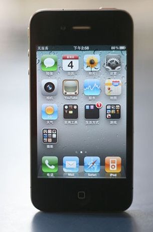
iPhone 4
However, to achieve this technology, whether it is conductive layer planning, routing or CPU computing, the difficulty is much improved, and a more powerful processor is needed. Take the iPhone as an example. It is to share the work with two independent chips. One sensing controller converts the original analog sensing signal into XY coordinate; the other is the ARM7 processor, which is specially used to interpret these. Information, identify finger movements, and respond accordingly. In addition, complex contact location technology will face some design challenges, such as the need to supply high voltage to get better signal-to-noise ratio performance, not suitable for large-size panels, etc., which is why the iPhone failed to adopt 4.0-level screen. one.
Of course, there is another multi-touch method, Multi-Touch Gesture, which, in layman's terms, is a multi-touch recognition gesture direction. What we see most now is the Multi-Touch Gesture, which means that when two fingers are touched, the direction of motion of the two fingers can be recognized, but the specific position cannot be determined, and operations such as zooming, panning, and rotating can be performed. This multi-touch implementation is relatively simple, and the axis coordinate mode can be achieved. Dividing ITO into X and Y axes can sense two touch operations, but sensing the touch and detecting the specific location of the touch are two concepts. The XY-axis touch screen can detect the second touch, but cannot know the exact location of the second touch. A single touch produces a single maximum on each axis to determine the location of the touch. If there is a second finger touching the screen, there will be two maxima on each axis. These two maximum values ​​can be generated by two different sets of touches, so the system cannot accurately determine.
Optical Cable Cross Connection Cabinet
Modular design of Optical Cable Cross Connection Cabinet(FDH,FOCC) provides the largest flexibility; satisfy the needs of the present and future development. The body using the stainless steel and surface using electrostatic spray so it has good corrosion resistance and anti-aging function, the wind protection class of the body achieves the IP66 level. The effect of defense dewing is excellent. The module tray can spin out of 90 degrees around the axis in the left front, and the bevel of the adapters within the module takes on 30 degrees. The clip-locked installation ensures the bending radius of the fiber directly and prevents the eyes from injury. Weld disk can spin out of 90 degrees, and then draw out, so it is convenient to construction, and also convenient to expansion and maintenance. Have doors in the front and back, have ample space for cabling, convenient to operation and maintenance. Have reliable device for fastness, peeling and grounding of the optical cables. Insulation resistance between high voltage protection earth and box20,000MΩ /500V (DC)
Communication Optical Cable Cross Connection Cabinet is interface equipment to contact trunk optical cable and wiring cable. It is compose of box, inside structure, optical fiber connector and some accessories. The function is to connect, store, dispatch and enlarge optical fiber. The material of box is cold-roll steel sheets, SMC fiber strengthen unsaturated polyester or stainless steel material. It has high resist destroy capacity, high strength, safety and stability. It has the device to bring optical cable, fix and protect. It has optical fiber termination device which could easy to splice, fix and maintain the optical cable fiber and optical cable fiber/optical fiber pigtail. At the same time, it has more space to store the surplus optical cable and fiber. Through the optical fiber connector, it could dispatch the fiber serial number of optical cable and change the transmission system route rapidly and expediently.

Cross Connection Cabinet, Optical Cable Cross Connection Cabinet, FDH, FOCC
NINGBO YULIANG TELECOM MUNICATIONS EQUIPMENT CO.,LTD. , https://www.yltelecom.com