Abstract: The continuous improvement of living standards has led to the gradual entry of cars into thousands of households. The pursuit of fashion personality makes the car owners pay their attention to dress up their car. The LED scanning screen of the car LED not only shows the personality, but also plays a warning role. There is even a nice name called the Ranger lamp. This paper introduces the design and production method of a car network scanning light. It mainly uses the common STC89C52RC MCU as the main controller, uses the optocoupler for signal conversion, and converts into eight groups of LED scanning lamps with the piranha LED strips purchased on the market. It can produce effects such as tailing and breathing, as well as expansion of functions such as chassis lights and wireless remote control.
Key words: automobile; LED scanning lamp; optocoupler; single chip microcomputer; STC89C52RC
This article refers to the address: http://
0 Introduction The rapid development of the LED industry has brought a lot of impact to lighting and decoration, especially the combination of LED and automobile is currently a hot topic. Reading lights, width lights, brake lights, and even headlights in cars have gradually appeared in LEDs. Of course, as a decorative instrument light, scanning lights and chassis lights are not far behind, this paper introduces the design and production of an LED scanning light.
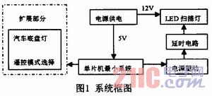
1 System configuration The system consists of a high-brightness LED light bar and a car network scanning light controller. The controller also includes a logic control (MCU minimum system) part, a power supply part, a power supply part, and a circuit delay part. The specific block diagram is shown in Figure 1.
2 circuit design Figure 2 is the logic control part of this design, using the classic 8051 MCU minimum system, model STC89C52RC, STC series MCU is most convenient to leave only P3.0 and P3.1 pin pins, The program can be downloaded to the MCU through the serial RS232 circuit of any experiment board, which is convenient for the modification and upgrade of the later works, and also provides convenience for debugging.
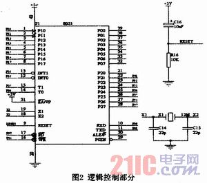
Need to pay attention to is that the 31 pin of the MCU must be connected to the high level, otherwise the MCU will not read the memory inside the chip, causing the MCU to not work. The 40-pin single-chip microcomputer used here is a bit too large, but the pins are led out to facilitate the expansion of the function in the future.
Figure 3 is the power supply part of the design. Because it involves separately supplying power to the high-brightness LED strip and the single-chip microcomputer, the power supply requires two voltage outputs of 12V and 5V. The car battery voltage is around 12.5V. The LED strip section can be powered directly from 12V. The part of the microcontroller needs 7805 to be converted to 5V voltage supply. In order to enhance the safety of the automotive circuit, a fuse is added to the power circuit. Among them, J2 is the input of the car power supply, the positive pole can be connected to the positive pole of the car width lamp, and the negative pole can be connected to the metal part of the car structure. J1 can be used to pull out the control switch or short out with a jumper cap.
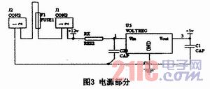
Figure 4 is the focus of this design, similar to the structure of Figure 4, there are three groups, the main components are optocouplers, the model can use EL817, using them to achieve electrical isolation, and achieve the use of single-chip signal control 12V lights Article. Two groups are selected, and the input terminal is connected with P2.7~P2.0 as the signal control end of the scanning lamp. It is used to control the eight sets of lights LED1~LED8 in the LED strip. It is worth noting that the input of the optocoupler is very fragile, and the current limiting resistor should be connected when accessing. The other end of the optocoupler can be connected to one of the LED strips, and form a loop with the 12V power supply, which is equivalent to the switch circuit controlled by the front internal LED. In the figure, the capacitors C2 to C5 function as a delay circuit. When the optocoupler is turned on, the group of LEDs is lit, and the capacitor is connected to the 12V power supply. When the optocoupler is turned off, the capacitor is combined with the group of LED lamps. Forming the discharge circuit, maintaining the set of lights is not extinguished immediately. The trailing effect of the scanning light is achieved by this part of the circuit. The third group of four optocouplers is used as an extension function.
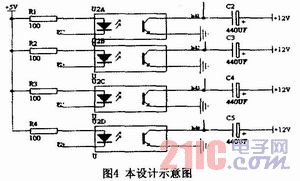
Figure 5 shows the design signal extraction port. The signal from J5 is used to control eight sets of car scanning lights. The four sets of LED signals from J4 are used to expand the chassis lights or breathing lights. J9 is connected to the P3 port of the single-chip microcomputer to expand the module such as wireless remote control or communication.
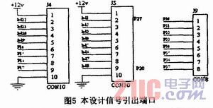
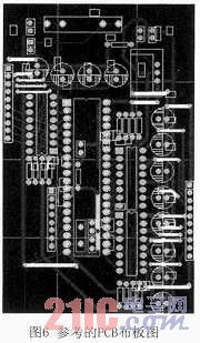
Figure 6 is a reference PCB layout diagram. The use of a single-sided copper-clad board increases the difficulty of wiring, and requires a large number of flying lines. If a double-layer board is used, the layout problem can be simplified a lot. In Figure 3, the RX can be selected with a 75 ohm high power resistor. Because the design uses a four-pin optocoupler, and the optocoupler is a component that can fail, a 16-pin IC socket is used on the package. This allows four optocouplers to be mounted per socket.
3 Component Selection Wires connected to the vehicle's power supply are recommended to use a suitable silicone insulated wire for high temperature and high current. The fuse can be 1A or 2A. The optocoupler selects the EL817, and the current limiting input must be connected to the optocoupler input. When doing the experiment, be careful not to burn the optocoupler due to excessive current. As a capacitor for delayed energy storage, choose a good 330UF or 470UF capacitor.
4 Installation and commissioning This design is easy to debug, just write the program of the water light or pattern light to the microcontroller. The data is output from the P2 port, that is, the port that connects the scanning lamp to control the optocoupler. It should be noted that the setting of the delay in the program should be modified according to the effect of the actual flash. As long as the chosen time is right, it will produce a tailing effect like a flame. The test uses 12.5V voltage, the highest current is only up to
150mA.
5 Precautions The car is moving and the engine compartment is also hot. Therefore, the installation environment of this design is an environment with high temperature and high vibration. Pay attention to shock and heat dissipation during installation. The power supply is taken from the car's width indicator so that the instrument panel can be operated as soon as it lights up.
6 Conclusion This article uses a simple idea to achieve a simple application of LED and microcontroller. Personalized makeup for the car. It also adds color to life.
RJ45 connectors mostly used for data communication . SVLEC provide Male Female straight angle .RJ45 shielded connector with 4-pole 8-pole , Protection degree IP20 with Quick connection technology .Plastic or metal housings with good resistance against chemicals and oils. The resistance to aggressive media should be individually tested for your application. Further details on request.
![}A(]M{5CKN@L01W(WDP`]PS }A(]M{5CKN@L01W(WDP`]PS](http://i.bosscdn.com/product/80/bf/88/c48b0c48b2c9627adb4dc02ce1.png)
Rj45 Connector,Rj45 Cat5 Connector,8Pin Rj45 Connector,RJ45 Shielded Connector, RJ45 connector 4 pin
Kunshan SVL Electric Co.,Ltd , https://www.svlelectric.com