We always hope that the coverage of the wireless coverage base station is as good as possible, but the transmission distance of the wireless system is also related to the technical specifications of the customer terminal equipment. The standard WiFi client has limited uplink power (typically 15dBm). Regardless of the downlink power of the wireless coverage base station, the uplink distance of the standard WiFi client is limited by the uplink power, and the distance is very limited. The wireless CPE is a dedicated client terminal device, and the distance between the wireless outdoor CPE and the wireless coverage base station can reach 4 times that of the standard WiFi client.
Of course, in practical applications, it is difficult to find an application environment where the line of sight is unobstructed. The measurement and practical experience of the wireless propagation model show that the transmission distance between the client and the base station using CPE can reach 1Km-5Km.
Wireless CPE is a wireless bridge that we often say. It is an outdoor wireless AP device, which is generally a point-to-point connection. It is responsible for transmitting one end of the network to the other end through wireless remotely. Most bridges use a 5.8G cleaner frequency band and 2.4G, but they have been deprecated due to excessive interference. The bridge is mainly used for outdoor monitoring, elevator monitoring, building network transmission and other places.
Tools/raw materialsWireless Bridge: LF-P588 P581 P591 Series
-Installation accessories: elevation bracket, triangle bracket, metal steel ring
- Setup tool: computer or mobile phone
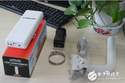
Method / step1 Purchase spare parts and mainframe, check whether the equipment is complete, bridge host, POE power adapter, metal steel ring, and bracket for mounting the pole. Here, the triangle bracket or the elevation bracket can be selected.
2 Before installing the pole, first set the parameters in the indoor bridge and then install the pole outside, set the connection, connect the network cable to the WAN port of the bridge, and connect the other end to the POE port of the POE power adapter, the LAN of the POE power supply.æŠ Connect to the computer network port. Note: The POE port of the power adapter is used to power and communicate the bridge, and the lan port is used to connect to a computer or router.
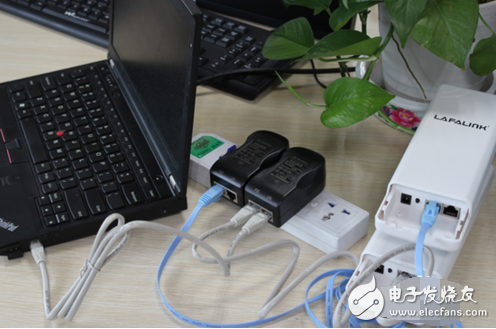
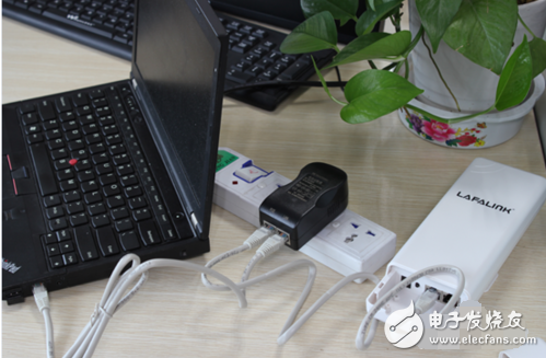
After the setting is completed, remove the network cable connected to the computer, connect to the gateway or switch on the front section, and take the bridge to the outdoor fixed location for pole installation.
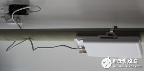
Use the triangular bracket to install the bridge. First install the U-coil through the nut to the pole. Then use the coil to fix the bridge. The bridge can adjust the angle up and down.
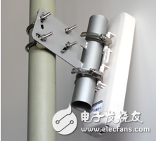
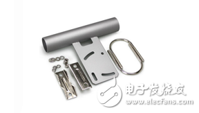
Use the elevation bracket to install, you can wall-hang or hold the pole. When hanging the wall, use the expansion screw to fix it on the wall. The bridge is fixed on the bracket by the coil, and the bridge angle can be adjusted through the bracket.
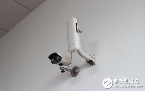
When the pole is installed, the bracket can be fixed to the pole by the coil, and then the bridge is fixed.
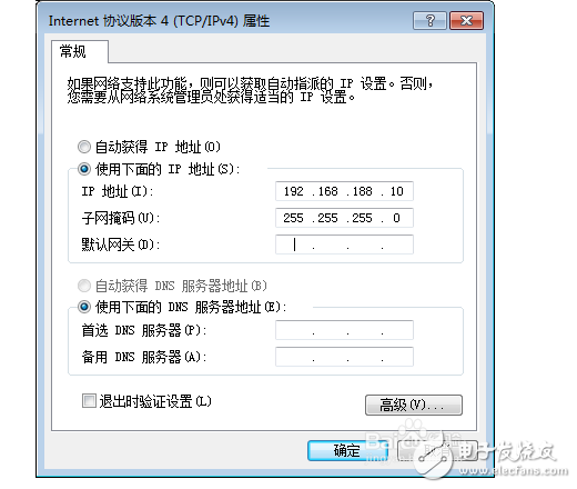
Open your computer's local connection, right click on Properties, select Protocol Version 4, and click Properties. The computer manually sets a 192.168.188.10 255.255.255.0 PS: only change the IP and mask, the others are empty.
Open a browser, type 192.168.188.253, press Enter to log in to the device management interface.

First take a bridge A as the transmitter setting, enter 192.168.188.253 in the browser, enter the device management interface.
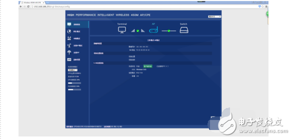
The transmitter bridge A defaults to the AP mode. The mode does not need to be changed, and the IP address is changed to static. Advanced Settings - Network Settings - Change DHCP to static IP. Just change the IP address, the other keeps the default, use the 188 network segment, it is not recommended to use other network segments. PS: Keep the transmitter powered on after setting.
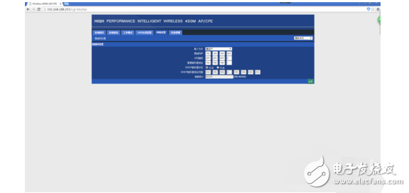
Receiver bridge B settings, same as step two, first change the IP address, advanced settings - network settings - change DHCP to static IP.
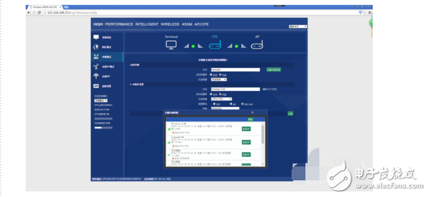
Test: The computer is connected to a bridge A. Try to change the management address of another bridge B in the browser. If you can enter the management interface of the B bridge, the bridge is good.
Precautions
Obstructions such as trees, tall buildings, and large steel buildings can weaken wireless signals during wireless transmission. In order to improve the wireless transmission performance and prevent the signal from being blocked, please ensure that the obstacles are blocked within the line of sight between the wireless CPEs during installation.
When installing a CPE device, adjust its front panel orientation to ensure that the receiving device is within its signal coverage. You can use the tools like Google Maps, GPS, etc., combined with the horizontal lobe width of the CPE device to determine the orientation of the CPE.
Set AP mode, or relay mode. Be sure to replace the bridge's DHCP with a static IP.
If you can't get on, try pinging 192.168.188.253, method: run --cmd--ping 192.168.188.253. If it works, it is recommended to replace it with Google Chrome. If you can't pass, you can try the one that plugs the bridge.
1 Problems faced by traditional outdoor coverageWhen the outdoor WLAN outdoor base station is used for the WLAN outdoor coverage, the WLAN outdoor base station AP is used to cover the target area, and the user terminal directly connects to the WLAN signal provided by the base station AP, as shown in FIG. 1 . This kind of coverage scheme faces many practical problems especially in the case of coverage of residential areas.
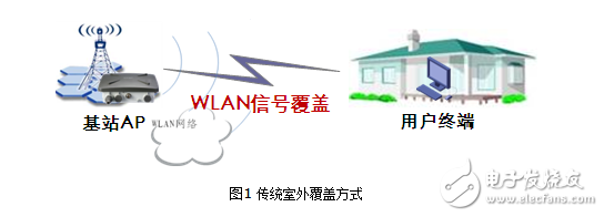
Figure 1 Traditional outdoor coverage
1.1 Uplink and downlink power mismatch problems
A high-power outdoor base station type AP can generally provide a maximum transmit power of 500 mW. In addition, a high-gain antenna can cover a distance of about 2 km, but the power of the WLAN terminal is small, generally around 20 mW, which results in a distance from the base station. In the farther place, although the terminal can receive the signal of the base station, the base station does not perceive the existence of the terminal, thereby causing the uplink and downlink power mismatch problem in the wireless communication. Just like the flashlight can see the lighthouse, but the light can not see the flashlight, as shown in Figure 2.
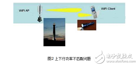
Figure 2 uplink and downlink power mismatch problem
1.2 Signal coverage quality problems after entering the room
When the residential building is covered by the method of outdoor base station coverage, due to the complicated structure of the building, the signal entering from the outdoor will be attenuated rapidly (as shown in Table 1). It is difficult to ensure the signal coverage of the indoor area, which may lead to the WLAN network. The user experience is poor.
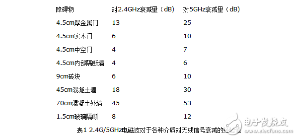
The concrete walls of the building have a very large loss of signal. From practical experience, it is difficult for the WLAN signal to pass through the two walls to ensure coverage.
2 Outdoor coverage CPE solutionIn the outdoor coverage CPE solution, a dedicated outdoor CPE device is used to establish a stable uplink WLAN link with the base station AP, as shown in FIG.

Since the maximum transmission power of the outdoor CPE can reach 500mw, which is much higher than the user terminal equipment and the built-in high-gain directional antenna, it can effectively solve the problem of power mismatch between the uplink and downlink signals, ensure the effective extension of the outdoor coverage signal, and fundamentally solve the rural The last mile of user broadband access.
At present, the outdoor coverage CPE solution has been applied in rural areas. Because such areas usually have less interference and better wireless air interface environment, the 2.4G frequency band is generally used as the WLAN uplink of the base station AP and the CPE terminal, and the base station AP can satisfy Coverage of approximately 1.5-2 km.
3 Base station AP and CPE deployment modeWhen the CPE is deployed in the 2.4G frequency band, up to three APs can be deployed on one base station at the same time. The three APs work on channels 1, 6, and 11 respectively. Each channel covers different channels. The direction of the formation of different coverage sectors, each sector is usually a broadband access user aggregation area of ​​different villages, as shown in Figure 4.
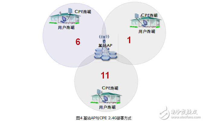
Note: If there are a large number of users in a certain sector, 2-3 APs can also cover the same sector at the same time. However, according to the actual distribution of broadband services, such deployment methods are rare.
4 High-density user area expansion solutionAfter the first phase of the outdoor CPE solution, the rural broadband subscriber service in a certain area has developed better. The number of online users has reached the upper limit of the service that can be carried by each AP base station. It is urgent to expand new users and needs to be built in the first phase (ie, the base station AP and The CPE 2.4G deployment method is based on the expansion of new users. Currently, capacity expansion can be achieved in the following two ways.
4.1 5G CPE Expansion Mode
Since the base station AP in the original scheme covers the CPE by using the 2.4G frequency band, it is limited by the frequency band resources, and only three APs can be deployed per base station. In order to expand new users, a new 5G frequency band can be introduced. The base station AP adopts dual-band AP for deployment and supports both 2.4G and 5G. Considering the attenuation and coverage of 2.4G and 5G signals, it is recommended that the base station AP 2.4G band covers the CPE in the far area, and the 5G band covers the nearer area. CPE, as shown in Figure 5.
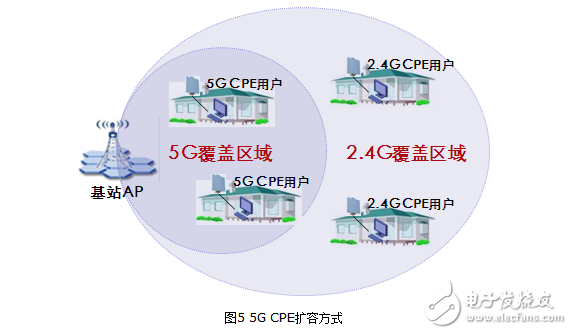
This scheme can greatly expand the frequency band resources (the 802.11n 5G frequency band is open in China and does not interfere with the 20MHz channel in China), which can effectively expand new users and facilitate subsequent channel planning and deployment. However, due to the addition of 5G coverage area, 5G needs to be added. CPE equipment, and new planning and adjustment of the distribution of the original 2.4G users.
4.2 5G bridge link backhaul expansion mode
5G bridge link backhaul expansion mode: By adding an AP in the original coverage area, a new cell is planned to increase the overall capacity of the system, and the number of access users is increased. The uplink of the newly added AP is backhauled by the 5.8G bridge link. In the mode, the CPE user is added to the downlink through the 2.4G. As shown in Figure 6, the dark area represents the area of ​​the AP coverage area.
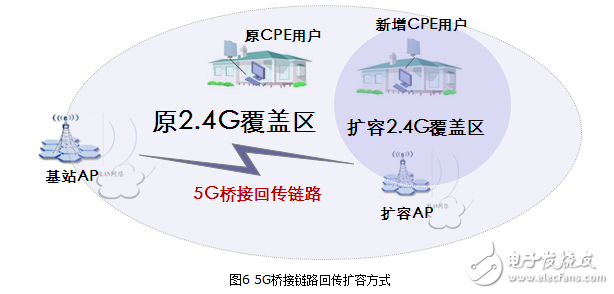
Because this solution expands the new 2.4G coverage area in the original 2.4G coverage area, it is necessary to use channel isolation with the highest isolation. For example, the original 1 channel sector uses 11 channels to expand, and the original 11 channel sector uses 1 channel expansion. In the case of meeting the coverage of the AP, the coverage of the AP should be effectively controlled by adjusting the AP transmit power to minimize the impact on other existing sector coverage areas.
At the same time, in order to ensure the quality of the 5G wireless bridge link, the distance between the expansion site and the original base station is recommended not to exceed 2km. The bridged AP must be visible and unobstructed, and the antenna installation height meets the requirements.
This expansion scheme still uses the 2.4G frequency band, so the capacity of the new expansion is limited. At the same time, in order to reduce the mutual influence between the 2.4G coverage areas, high requirements are imposed on engineering implementation and equipment debugging.
Special equipment for university physics laboratory
Teaching Equipment,Optical Bench Kit,Optical Instruments In Physics,Electrooptical Modulator Experimental Instrument
Yuheng Optics Co., Ltd.(Changchun) , https://www.yhencoder.com