The scope of application is used to test the DC resistance of transformers, motors, transformers and other equipment (test speed is fast, test results are printed intuitively).
Method of Use The grounding resistance tester refers to the earthing body resistance buried in the ground and the soil stray resistance. It is usually measured by a grounding resistance meter (or grounding resistance meter). The shape measuring instrument has the same shape as the ordinary insulated rocking watch, and is also called a grounding resistance shaking table according to custom. The shape of the shaker varies slightly depending on the model, but the method of use is basically the same. The type grounding resistance measuring instrument is provided with two grounding probes and three wires. The method of use and measurement steps are as follows:
(a) Grounding resistance tester (b) Connecting wire (c) Measuring grounding bar
1. Disconnect the grounding mains from the grounding body or disconnect the grounding points of all the grounding lines on the grounding mains.
2. Insert the two grounding rods into the ground 400mm deep, one far from the grounding body 40m, and the other 20m away from the grounding body.
3. Place the shaker in a flat place near the grounding body and wire it.
(1) Connect the Terminal Block E on the watch and the grounding body E' of the grounding device with a connecting wire.
(2) Connect the terminal block C on the watch to the grounding rod C' which is 40m away from the grounding body with a connecting wire.
(3) Connect the terminal block P on the watch and the ground bar P' 20m away from the grounding body with a connecting wire.
4. According to the grounding resistance requirements of the grounding body to be tested, adjust the coarse adjustment knob (the upper three adjustable range).
5. Shake the table evenly at a speed of about 120 rpm. When the hands are deflected, adjust the fine adjustment dial until the hands are centered. Use the fine adjustment dial to adjust the reading, multiply by the coarse adjustment multiple, which is the grounding resistance of the grounded body to be tested. For example, if the fine-tuning reading is 0.6 and the coarse tuning resistance is 10, the measured grounding resistance is 6Ω.
6. In order to ensure the reliability of the measured grounding resistance value, the orientation should be changed and the retesting should be performed. Take the average of several measured values ​​as the grounding resistance of the grounding body.
Before operating the measurement, first make sure that the surface to be tested is clean and free from contamination.
Surface impedance
1, parallel probe impedance measurement method (Parallel Probe ResistivityMethod)
The parallel probe impedance measurement method is a measurement method conforming to the EOS/ESD-S11.11-1993 standard, which is a rapid method for measuring the resistance value of a planar uniform material. This method is also suitable for the measurement of multilayer materials, but the temperature and humidity conditions at the time of measurement must be indicated in the impedance value report. A. Place the watch on the surface of the object to be measured.
B. Adjust the switch to the desired voltage position (10 volts or 100 volts)
C. Press and hold the measurement button with a pressure of approximately 5 lbs. The LCD screen will display the measured surface impedance, temperature and relative humidity values. The entire measurement process is approximately fifteen seconds.
·The surface impedance unit is ohm / □
·The temperature unit is the camera type. The relative humidity unit is the percentage. In each measurement, after the measurement button is pressed, the tester will continuously display the trimming measurement value. Within about forty-five seconds after the button is released, the last measurement is displayed. value.
2, Conncentric Ring Probe Resistivity method (concentric ring probe is optional)
Plug the cable plug into the two 3.5 mm jacks on the meter and connect the banana plug to the concentric ring probe (optional). After placing the probe on the surface of the object to be tested, press the button for about 15 seconds, the correct temperature and relative humidity will be displayed on the LCD. The correct surface impedance value is multiplied by 10 on the LCD. The unit is ohm / â–¡. E.g:
The crystal screen shows 3.5×10 4 ohms/□; the actual impedance value is 3.5×10 5 ohms/□.
Calibration step
1. Range 10 3 to 10 12 Impedance bridge with 1% accuracy. High-precision relative humidity meter (Relative Humidity Hygrometer) High accuracy Thermometer
2. Open the cover and be careful not to damage the two wires connecting the power switch on the board.
3. Find the three calibration regulators at the bottom right of the board (Calibration Pots)
4. Make the watch at least 1/2 hour under this environmental condition, and then start self-balancing before starting the test.
5. Connect one end of the connecting cable of the tester to the alligator clip and the other end to the banana plug.
6. Insert the 3.5 mm long plug into the socket of the meter.
7. Connect the two ends of the resistor with an alligator clip.
8. Three calibration regulators, the uppermost is the "humidity" measurement, the middle is the "impedance", and the bottom is the "temperature adjustment with a small screwdriver." The clockwise direction is the increase value adjustment, and the counterclockwise direction is the decrease value adjustment.
9. Press the power switch and compare the "temperature", "humidity" and "resistance" values.
10. Release the power switch and slowly adjust the corresponding calibration regulator.
11. Press the power switch again to observe the LCD display.
12. If you need to recalibrate, press the power switch and adjust the corrector.
13. Cover the cover and tighten the four fixing screws.
14. Press the power switch to determine if the meter is working properly.
Resistance tester usage
1) Read the instruction manual of the grounding resistance measuring instrument, and fully understand the structure, performance and usage of the instrument.
2) Prepare the necessary tools and all instrument accessories for the measurement, and wipe the instrument and grounding probe cleanly, especially the grounding probe. Be sure to clean the dirt and rust stains whose surface affects the conductivity.
Antenk manufactures a wide range of application specific board stacking connectors which were designed and built to specific customer requirements. Our experienced staff has developed custom products in a variety of contact styles, pitches and stacking heights. Our designs range from new concepts to duplicating existing market products identically or with improvements. Many desigsn are produced using automated manufacturing processes to increase reliability and provide significant cost savings
Board to Board Connector
Board-to-board (BTB) connectors as the name indicates is used for connecting circuits board together. This kind of connectors are suitable for stacking circuits boards one over another. Flat flexible cables can be avoided using these kinds of connectors; moreover it makes the entire unit more compact. The commonly used BTB connectors are SMT connectors and Berg Strip. We will discuss about them in detail in the following section.
SMT CONNECTOR
Surface Mount Technology (SMT) connector is a commonly found board-to-board connector in advanced circuit boards. As the name indicates this connector is available only in surface mount model. It is carefully mounted on to the solder pads on the surface of the PCB.
SMT connectors are ideal candidate for miniaturization due to their small area of occupancy and stacking height. They are suitable for double layered or multilayered PCBs. They are designed for high performance and reliability.
They commonly found in advanced circuit boards in networking equipment, telephones, mobile phones, computers and other consumer electronics.
Board-to-board (BTB) connectors are used to connect printed circuit boards (PCB), electronic components that contain a conductive pattern printed on the surface of the insulating base in an accurate and repeatable manner. Each terminal on a BTB connector is connected to a PCB. A BTB connector includes housing and a specific number of terminals. The terminal is made from a conductive material (mostly copper alloy), and plated to improve conductivity and antirust. Terminals transmit the current/signal between PCBs connected by BTB; the housing is made of insulating material (mostly plastic).
The basic types of Board to Board Connector
Broadly speaking, board to board connectors are manufactured in the following types:
Pin Header
Elevated Pin Header
Socket
Elevated Socket
Shrouded Header
Box Header

The way mount Board to Board Connectors on a PCB
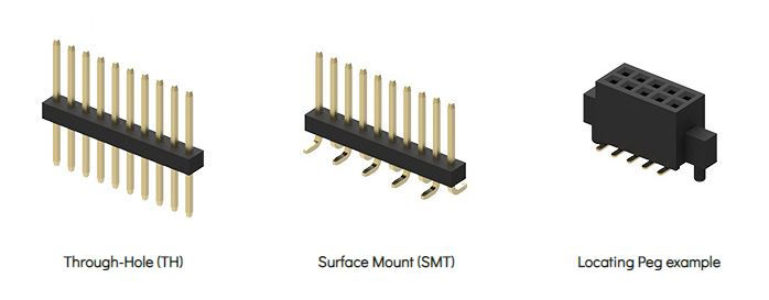
board to board connectors are available in through hole (TH) and Surface Mount (SMT) variants.
Locating pegs (also referred to as locating posts, alignment pins or board locks) are used to assist alignment of connectors to the PCB. Locating pegs are particularly useful when using surface mount components.

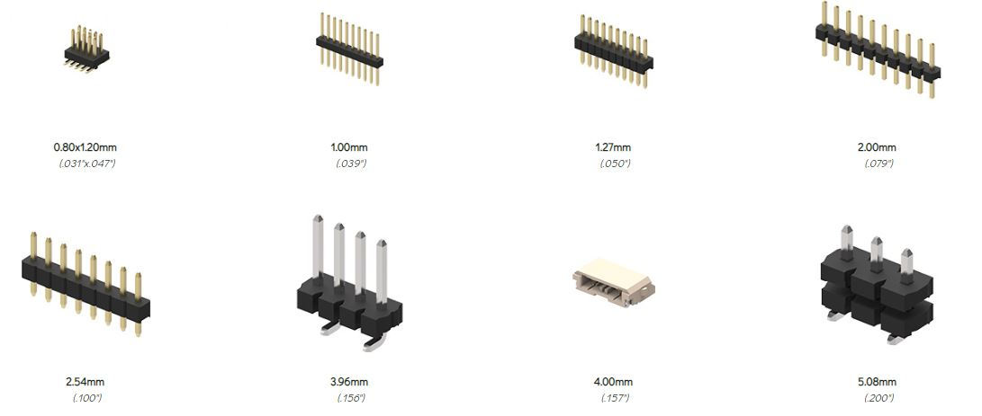
board to board connectors are available in the following pitches: 04mm/0.5mm/0.8mm/1.0mm/1.27mm/2.54mm/3.96mm/4.0mm
For experienced hardware designers choosing board to board connectors is second nature, for the uninitiated it can be daunting. We offer design support and will help guide you through the options available. If you need help with your board to board connector design, contact antenk. Where required antenk also offer non standard pitches.

0.4mm Board To Board Connectors,0.5mm Female Board To Board Connector,0.8mm 1.0 mmPcb Board To Board Connector,Board To Board Terminal Connectors
ShenZhen Antenk Electronics Co,Ltd , https://www.antenk.com